

Introduction to 3D Game Programming with DirectX.9.0 - F. D. Luna
.pdf144 Chapter 8
Finally, we are ready to draw the reflected teapot:
Device->SetTransform(D3DTS_WORLD, &W);
Device->SetMaterial(&TeapotMtrl);
Device->SetTexture(0, 0);
Device->SetRenderState(D3DRS_CULLMODE, D3DCULL_CW);
Teapot->DrawSubset(0);
Recall from section 8.2.3.4 that W correctly transforms the reflected
teapot into its appropriate position in the scene. Also, observe that we change the backface cull mode. We must do this because when an
faces will have a winding order that indicatesYto Direct3D that they are
object is reflected, its front faces will be swapped with its back faces;
however, the winding order will not be changed. Thus, the “new” front
Device->SetRenderState(D3DRS_ALPHABLENDENABLE, false);
Device->SetRenderState( D3DRS_STENCILENABLE, false);
Device->SetRenderState(D3DRS_CULLMODE, D3DCULL_CCW);
back facing. Similarly, the “new” back-facing triangles will have a wind- |
||
|
|
L |
ing order that indicates to Direct3D that they are front facing. |
||
|
|
F |
Therefore, to correct this, we must change our backface culling |
||
condition. |
|
|
Cleaning up, we disableMblending and stenciling and restore the |
||
usual cull mode: |
A |
|
|
|
|
|
|
E |
|
T |
|
}// end RenderMirror()
8.3Sample Application: Planar Shadows
Shadows aid in our perception of where light is being emitted in a scene and ultimately makes the scene more realistic. In this section we show how to implement planar shadows—that is, shadows that lie on a plane (see Figure 8.5).
Figure 8.5: A screen shot taken from this chapter’s sample application.
Notice the teapot’s shadow on the floor.
Team-Fly®
Stenciling 145
Note that these types of shadows are a quick hack, and although they enhance the scene, they aren’t as realistic as shadow volumes. Shadow volumes are an advanced concept that we feel is best left out of an introductory book. However, it is worth mentioning that the DirectX SDK has a sample program that demonstrates shadow volumes.
To implement planar shadows, we must first find the shadow that an object casts to a plane and model it geometrically so that we can render it. This can easily be done with some 3D math. We then render the polygons that describe the shadow with a black material at 50% transparency. Rendering the shadow like this can introduce some artifacts, namely “double blending,” which we explain in a few sections. We employ the stencil buffer to prevent double blending from occurring.
8.3.1 Parallel Light Shadows
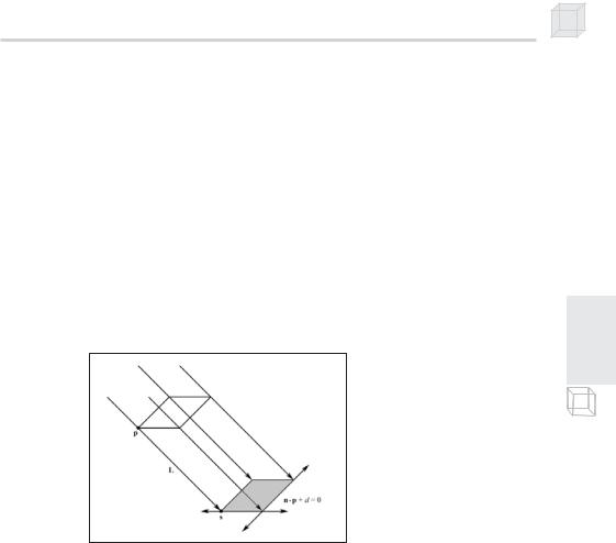
Figure 8.6: The shadow cast with respect to a parallel light source
Figure 8.6 shows the shadow that an object casts with respect to a parallel light source. The light ray from a parallel light, with direction L, through any vertex p is given by r(t) = p + tL. The intersection of the ray r(t) with the plane n p + d = 0 gives s. The set of intersection points found by shooting r(t) through each of the object’s vertices with the plane defines the geometry of the shadow. An intersection point s is easily found with a ray/plane intersection test:
n p tL d 0 Plugging r(t) into the plane equation n p + d = 0
n p t n L d
t n L d n p Solving for t
t d n p n L
P a r t I I
146 Chapter 8
Then:
d n p |
||
s p |
n L |
L |
|
|
|
8.3.2 Point Light Shadows
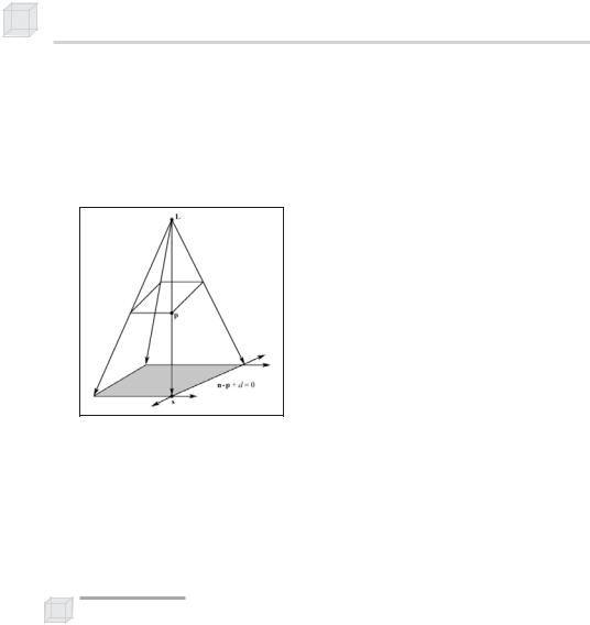
Figure 8.7: The shadow cast with respect to a point light source
Figure 8.7 shows the shadow that an object casts with respect to a point light source whose position is described by the point L. The light ray from a point light through any vertex p is given by r(t) = p + t(p – L). The intersection point of the ray r(t) with the plane n p + d = 0 gives s. The set of intersection points found by shooting r(t) through each of the object’s vertices with the plane defines the geometry of the shadow. s can be solved for using the same technique (plane/ray intersection) used in section 8.3.1.
Note: Notice that L serves different purposes for point and parallel lights. For point lights we use L to define the position of the point light. For parallel lights we use L to define the direction of the parallel light rays.
8.3.3 The Shadow Matrix
Notice from Figure 8.6 that for a parallel light, the shadow is essentially a parallel projection of the object onto the plane n p + d = 0 in the specified light direction. Similarly, Figure 8.7 shows that for a point light, the shadow is essentially a perspective projection of the object onto the plane n p + d = 0 from the viewpoint of the light source.
We can represent the transformation from a vertex p to its projection s with the plane n p + d = 0 with a matrix. Moreover, we can represent both an orthogonal projection and a perspective projection with the same matrix using some ingenuity.

Stenciling 147
Let (nx, ny, nz, d) be a 4D vector representing the coefficients of the general plane equation describing the plane that we wish to cast the shadow onto. Let L = (Lx, Ly, Lz, Lw) be a 4D vector describing either the direction of a parallel light or the location of a point light. We use the w coordinate to denote which:
1.If w = 0, then L describes the direction of the parallel light.
2.If w = 1, then L describes the location of the point light.
Assuming the normal of the plane is normalized, we let k = (nx, ny, nz, d) (Lx, Ly, Lz, Lw) = nxLx + nyLy + nzLz + dLw.
Then we represent the transformation from a vertex p to its projection s with the following shadow matrix:
nx Lx k |
nx Ly |
|
nx Lz |
nx Lw |
|
||||||||||||||||
|
n |
L |
|
n |
L |
|
k |
|
n |
|
L |
|
n |
L |
|
|
|||||
S |
y |
L |
x |
y |
|
|
y |
L |
|
n |
|
y |
|
|
z |
n |
y |
L |
w |
|
|
|
n |
|
n |
|
|
|
|
L |
|
|
k |
|
|
|
|||||||
|
y |
|
x |
|
|
z |
|
y |
|
z |
|
z |
|
|
|
z |
|
w |
|
||
|
dLx |
|
dLy |
|
|
dLz |
dLw |
k |
|||||||||||||
Because it’s been done elsewhere and not of significant importance to us, we do not show how to derive this matrix. However, for the interested reader, we refer you to Chapter 6, “Me and My (Fake) Shadow,” of Jim Blinn’s Corner: A Trip Down the Graphics Pipeline, which shows how this matrix can be derived.
The D3DX library provides the following function to build the shadow matrix given the plane that we wish to project the shadow to and a vector describing a parallel light if w = 0 or a point light if w = 1:
D3DXMATRIX *D3DXMatrixShadow(
D3DXMATRIX *pOut,
CONST D3DXVECTOR4 *pLight, // L
CONST D3DXPLANE *pPlane |
// plane to cast shadow onto |
);
8.3.4 Using the Stencil Buffer to Prevent Double Blending
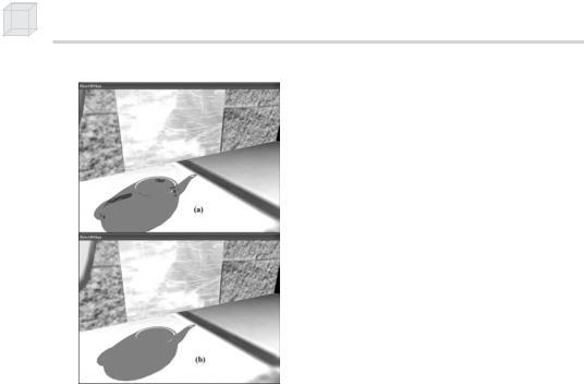
When we flatten out the geometry of an object onto the plane to describe its shadow, it is possible that two or more of the flattened triangles will overlap. When we render the shadow with transparency (using blending), these areas that have overlapping triangles will get blended multiple times and thus appear darker. Figure 8.8 shows this.
P a r t I I
148 Chapter 8
Figure 8.8: Notice the “black” areas of the shadow in (a). These correspond to areas where parts of the flattened teapot overlap, causing a “double blend.” Image (b) shows the shadow rendered correctly without double blending.
We can solve this problem using the stencil buffer. We set the stencil test to only accept pixels the first time they are rendered. That is, as we render the shadow’s pixels to the back buffer, we mark the corresponding stencil buffer entries. Then, if we attempt to write a pixel to an area that has already been rendered to (marked in the stencil buffer), the stencil test will fail. In this way, we prevent writing overlapping pixels and therefore avoid double blending artifacts.
8.3.5 Code and Explanation
The following code explanation is taken from the Shadow sample in the companion files. The code relevant to this sample lies in the RenderShadow function. Note that we assume the stencil buffer has already been cleared to zero.
We begin by setting the stencil render states. We set the stencil comparison function to D3DCMP_EQUAL and the D3DRS_STENCILREF render state to 0x0, thereby specifying to render the shadow to the back buffer if the corresponding entry in the stencil buffer equals 0x0.
Since the stencil buffer is cleared to zero (0x0), this will always be true the first time we write a particular pixel of the shadow; but because we set D3DRS_STENCILPASS to D3DSTENCILOP_INCR, the test will fail if we try to write to a pixel that we have already written to. The pixel’s stencil entry will have been incremented to 0x1 the first time it was written to, and thus the stencil test will fail if we try to

Stenciling
write to it again. Hence, we avoid overwriting a pixel and thus avoid double blending.
void RenderShadow()
{
Device->SetRenderState(D3DRS_STENCILENABLE, true); Device->SetRenderState(D3DRS_STENCILFUNC, D3DCMP_EQUAL); Device->SetRenderState(D3DRS_STENCILREF, 0x0); Device->SetRenderState(D3DRS_STENCILMASK, 0xffffffff); Device->SetRenderState(D3DRS_STENCILWRITEMASK, 0xffffffff); Device->SetRenderState(D3DRS_STENCILZFAIL, D3DSTENCILOP_KEEP); Device->SetRenderState(D3DRS_STENCILFAIL, D3DSTENCILOP_KEEP); Device->SetRenderState(D3DRS_STENCILPASS, D3DSTENCILOP_INCR);
Next, we compute the shadow transformation and translate the shadow into the appropriate place in the scene.
//compute the transformation to flatten the teapot into
//a shadow.
D3DXVECTOR4 lightDirection(0.707f, -0.707f, 0.707f, 0.0f); D3DXPLANE groundPlane(0.0f, -1.0f, 0.0f, 0.0f);
D3DXMATRIX S;
D3DXMatrixShadow(&S, &lightDirection, &groundPlane);
D3DXMATRIX T;
D3DXMatrixTranslation(&T, TeapotPosition.x, TeapotPosition.y,
TeapotPosition.z);
D3DXMATRIX W = T * S;
Device->SetTransform(D3DTS_WORLD, &W);
Lastly, we set a black material at 50% transparency, disable depth testing, render the shadow, and then clean up by re-enabling the depth buffer and disabling alpha blending and stencil testing. We disable the depth buffer to prevent z-fighting, which is a visual artifact that occurs when two different surfaces have the same depth values in the depth buffer; the depth buffer doesn’t know which should be in front of the other, and an annoying flicker occurs. Because the shadow and floor lie on the same plane, z-fighting between them will most likely occur. By rendering the floor first and the shadow after with depth testing disabled, we guarantee our shadow will be drawn over the floor.
Note: An alternative method for preventing z-fighting is to use the Direct3D depth bias mechanism. See the D3DRS_DEPTHBIAS and D3DRS_SLOPESCALEDEPTHBIAS render states in the SDK documentation for details.
Device->SetRenderState(D3DRS_ALPHABLENDENABLE, true); Device->SetRenderState(D3DRS_SRCBLEND, D3DBLEND_SRCALPHA);
Device->SetRenderState(D3DRS_DESTBLEND, D3DBLEND_INVSRCALPHA);
149
P a r t I I

150 Chapter 8
D3DMATERIAL9 mtrl = d3d::InitMtrl(d3d::BLACK, d3d::BLACK, d3d::BLACK, d3d::BLACK, 0.0f);
mtrl.Diffuse.a = 0.5f; // 50% transparency.
//Disable depth buffer so that z-fighting doesn't occur when we
//render the shadow on top of the floor.
Device->SetRenderState(D3DRS_ZENABLE, false);
Device->SetMaterial(&mtrl);
Device->SetTexture(0, 0);
Teapot->DrawSubset(0);
Device->SetRenderState(D3DRS_ZENABLE, true);
Device->SetRenderState(D3DRS_ALPHABLENDENABLE, false);
Device->SetRenderState(D3DRS_STENCILENABLE, false);
}//end RenderShadow()
8.4Summary
The stencil buffer and depth buffer share the same surface and are therefore created at the same time. We specify the format of the depth/stencil surface using the D3DFORMAT types.
Stenciling is used to block certain pixels from being rasterized. As we have seen in this chapter, this ability is useful for implementing mirrors and shadows among other applications.
We can control stenciling operations and how the stencil buffer is updated through the D3DRS_STENCIL* render states.
Some other applications that can be implemented with the stencil buffer:
Shadow volumes
Dissolves and fades
Visualizing depth complexity
Outlines and silhouettes
Constructive solid geometry
Fixing z-fighting caused by coplanar geometry

Part III
Applied Direct3D
In this part, we focus on applying Direct3D to implement several 3D applications, demonstrating techniques such as terrain rendering, particle systems, picking, and building a flexible 3D camera. In addition, we spend some time further exploring the D3DX library (in particular, the mesh-related components). A brief description of the chapters in this part follows.
Chapter 9, “Fonts”—During a game we often need to display textual information to the user. This chapter discusses three ways that we can generate and output text in Direct3D.
Chapter 10, “Meshes Part I”—This chapter thoroughly explains the data and methods of the D3DX mesh interface ID3DXMesh.
Chapter 11, “Meshes Part II”—In this chapter, we continue our study of the D3DX mesh-related interfaces and functions. We learn about .X files and how to load and render them. In addition, we examine the progressive mesh interface ID3DXPMesh. The chapter also shows how to compute the bounding box and bounding sphere of a mesh.
Chapter 12, “Building a Flexible Camera Class”—In this chapter, we design and implement a flexible camera class that has six degrees of freedom. This camera is suited for flight simulators and first-person shooters.
Chapter 13, “Basic Terrain Rendering”—This chapter shows how to create, texture, light, and render 3D terrains. Furthermore, we show how to smoothly “walk” the camera over the terrain so that it looks like we are walking on the terrain.
Chapter 14, “Particle Systems”—In this chapter, we learn how to model systems that consist of many small particles that all behave in a similar manner. For example, particle systems can be used to model falling snow and rain, the sparks of an explosion, puffs of smoke, rocket trails, and even the bullets of a gun.
151

152 Part III
Chapter 15, “Picking”—This chapter shows how to determine the particular 3D object that the user has selected with the mouse. Picking is often a necessity in 3D games and applications where the user interacts with the 3D world with the mouse.

Chapter 9
Fonts
During a game we often need to display textual information to the user. This chapter discusses three ways that we can generate and output text in Direct3D. Each way has a corresponding sample application on the web page for this chapter and in the companion files.
Objectives
To learn how to render text using the ID3DXFont interface
To learn how to render text using the CD3DFont class
To learn how to calculate the number of frames rendered per second
To learn how to create and render 3D text using the
D3DXCreateText function
9.1ID3DXFont
The D3DX library provides the ID3DXFont interface that can be used to draw text in a Direct3D application. This interface uses GDI internally to draw the text, and so we take a performance hit using this interface. However, ID3DXFont can handle complex fonts and formatting because it uses GDI.
9.1.1 Creating an ID3DXFont
We can create an ID3DXFont interface using the D3DXCreateFontIndirect function.
HRESULT D3DXCreateFontIndirect( |
|
LPDIRECT3DDEVICE9 pDevice, |
// device to be associated with |
|
// the font |
CONST LOGFONT* pLogFont, |
// LOGFONT structure describing |
|
// the font |
LPD3DXFONT* ppFont |
// return the created font |
); |
|
153