

3.3 Methodical instructions
3.3.1 It should be mentioned, that zone of intermittent currents exists at relatively small values of rectified current and from the fact that induction in the loading net of the convertor is the finite quantity, and as the result loading current is smoothed non-ideal [7]. Thus between continuous and intermittent current exists initially-continuous current mode, i.e. limiting mode. It is characterized by the fact that valves covering is absent, but there is no zero current intervals yet, as shown in the figure 3.5 а), as well as current at the beginning of each interval (at the moment of opening of next valve) is equal to zero. Thus voltage of converter exactly correspond to its e.m.f.
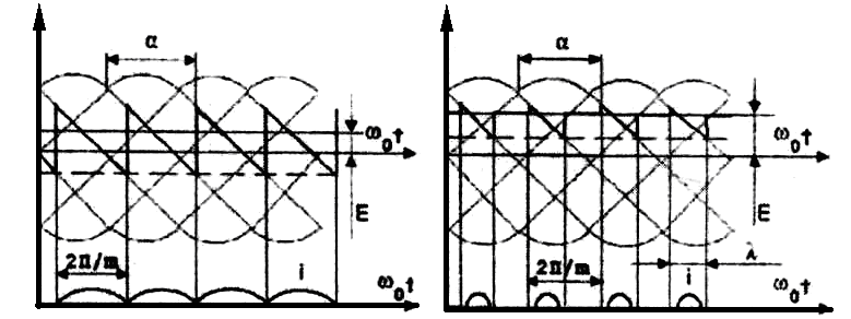
а) b)
Figure 3.5 – Diagram of e.m.f. and currents of thyristor converter in limiting a) and intermittent b) modes.
E.m.f. and currents of converter and also motor velocity for the intermitting current mode at the variable α and λ, might be calculated by the formulas:
![]() ; (3.1)
; (3.1)
![]() , (3.2)
, (3.2)
![]() . (3.3)
. (3.3)
In expressions (3.1)-(3.3) the following designations are used:
Ed is e.m.f. of convertor;
E2λmax
is
the
amplitude
value
of
liner
e.m.f.
of
transformer,
![]() ;
;
α is the angle of valve opening;
λ is the angular duration of impulse;
m is phase phenomena of convertor;
Id is the rectified current of convertor (current of the motor armature);
ω0 is angular frequency of the source;
LΣ is the inductance of armature circuit, which consists of two phases of transformer and inductance of the motor armature;
ωД is the angular velocity of the motor;
СД is the e.m.f. coefficient of the motor.
![]() ;
(3.4)
;
(3.4)
![]() ; (3.5)
; (3.5)
![]() ,
(3.6)
,
(3.6)
where
![]() ;
;
Ха is reactance of the transformer phase:
![]() ; (3.7)
; (3.7)
UK is short-circuit voltage of the transformer, UK=6%;
Іф.тр.=Інд;
ωн
is
the nominal velocity of the motor,
![]() ;
;
p= 2 is the number of pole pairs of the motor;
![]() ; (3.8)
; (3.8)
![]() ,
,
![]() is
active resistance of the armature circuit during intermittent
current.
is
active resistance of the armature circuit during intermittent
current.
Obtained dependence values of intermittent current and velocities (3.2), (3.3) from the value of valve opening angle and the angular current pulse duration is graphically presented by ellipse (Fig. 3.2), which must be drawn into e.m.f. graphs of convertor:
![]() .
.
3.3.2
During
loading of the motor,
which correspond to continuous current,
electromechanical characteristics
![]() and
mechanical characteristics
and
mechanical characteristics![]() can
be considered as linear and are calculated by the formulas
can
be considered as linear and are calculated by the formulas
![]() ; (3.10)
; (3.10)
![]() , (3.11)
, (3.11)
where Еdmax is maximal value of rectified e.m.f. of the convertor at α=0.
During СеФ = СмФ = Сд the equations (3.10), (3.11) will look like:
![]() ;
(3.12)
;
(3.12)
![]() .
(3.13)
.
(3.13)
At m = 6, α = 0 and λ = π/m from (3.1) we obtain:
![]() , (3.14)
, (3.14)
where![]() .
.
![]() .
.
Total
active resistance of the armature circuit:
![]() .
In
the
expression
(3.11) the
active
resistance
consists
of
motor
resistance
Rд,
commutation
resistance
Rк
and
the resistance of transformer phases,
which
because
of its small value can
be neglected.
Commutation
resistance:
.
In
the
expression
(3.11) the
active
resistance
consists
of
motor
resistance
Rд,
commutation
resistance
Rк
and
the resistance of transformer phases,
which
because
of its small value can
be neglected.
Commutation
resistance:![]() .
.
Calculation and construction of electromechanical characteristic we calculate by (3.12) for the continuous current mode we need to define for values Idгpmax, Idн, 0.5Idн. The value of Іdгpmax is determined by substitution into (3.2) m=6, α=π/2, λ=2π/m:
![]() .
.
Since:
 ,
where
,
where
![]() ,
,
then
Idгpmax= 276,6 (1 - 0,524·1,732)/314LΣ = 8,2·10-2 /LΣ.
For characteristic (3.13) its also necessary to take into account three moment values Mгpmax, 0.5Mн, Mн, where Мгpmax=Сд·Іdгpmax, and Mн=Сд·Ін.
3.3.3 Speed regulation upward from basis is realized by decreasing of excitation flow. Mechanical characteristics for this mode are necessary to built only in engine mode. They are determined by the expression (3.13) at α = const, which corresponds to the nominal mode of the motor. New values of constructive motor constant should be taken into account
 , (3.15)
And so-called angular coefficients of mechanical characteristic tgγ, which are determined in the item 3.3.4. Speed regulation in that range provides the continuity of capacity on the motor shaft, that’s why individual points, that limit the zone of admissible continuous moments (Fig. 3.4) is determined from the expression М = РH/ω.
Zone of intermittent currents is now defined by two straight lines: ordinate axis and line, which is parallel to it and passing through the point of limit current on the main motor characteristic.
3.3.4 New value of Сд' in the relevant characteristic is determined with:
 .
.
Solving this equation relatively to the Сд':
 .
.
And taking into account, that М∙ωд = Рн, we obtain:
![]() .
.
Because the engine runs in the system ТП-Д, then instead of U=Uн its necessary to substitute into the equation e.m.f. of convertor Edн, which provides a nominal mode of motor:
![]() ,
,
where Ен is the e.m.f. of the motor at nominal mode, V;
Idн is the nominal current of the armature, А.
Thus
at
known
Еdн,
RΣ,
Рн
some
constant
К is
calculated, for the chosen variant of the task
![]() and according to it dependence
and according to it dependence
![]() .
.
Taking
into account,
that![]() ,
we
obtain the anguler coeficient
,
we
obtain the anguler coeficient
 ,
,
where mM, mω are scales of the moment and velocity.
All calculation results are shown in the table 3.2.
Table 3.2 – Calculation results.
ωд,с-1 |
М=Рн/ωд, Нм |
Cд’=К/ωд |
Cд’2 |
RΣ/ Cд’2 |
tgγ |
1,2ωн |
|
|
|
|
|
1,Зωн |
|
|
|
|
|
1,4ωн |
|
|
|
|
|
1,5 ωн |
|
|
|
|
|
1,6ωн |
|
|
|
|
|
3.3.5 E.m.f., current and velocities for intermittent current modes should be calculated, and take individual values of variables α and λ, shown in (Table 3.3).
Table 3.3 – Calculation result of e.m.f., current and velocity for intermittent current modes.
Value |
α, rad |
λ,rad |
|||
π/12 |
π/6 |
π/4 |
π/З |
||
Еd, V Іd, А ω, с-1 |
π /12 |
|
|
|
|
π /6 |
|
|
|
|
|
π /4 |
|
|
|
|
|
π /З |
|
|
|
|
|
5 π /12 |
|
|
|
|
|
π /2 |
|
|
|
|
|
7 π /12 |
|
|
|
|
|
2 π /3 |
|
|
|
|
|
З π /4 |
|
|
|
|
|
5 π /6 |
|
|
|
|
|
11 π /12 |
|
|
|
|
|
π |
|
|
|
|
|
In explanatory note there must be three individual tables. Calculation results of moment Мгр = СдIdгр for intermittent current zone its enough to show for the next values of α and λ, given in the (Table 3.4).
Table 3.4 Calculation results of moment for intermittent current zone.
Value |
α, rad |
λ,rad |
|||
π/12 |
π/6 |
π/4 |
π/З |
||
М, Nm |
π /12 |
|
|
|
|
π /6 |
|
|
|
|
|
π /4 |
|
|
|
|
|
π /З |
|
|
|
|
|
5 π /12 |
|
|
|
|
|
π /2 |
|
|
|
|
|
3.3.6 Calculation results of velocity and moment in intermittent current zone for construction of electromechanical and mechanical characteristics are shown in the Table 3.5, 3.6.
3.3.6 Results and computing speed moment in the continuous current for the construction of electromechanical and mechanical characteristics cited in the table. 3.5, 3.6. Table 3.5 - Results of calculations of electromechanical characteristics.
Table 3.5 Calculation results of electromechanical characteristic.
Value |
α, rad |
Id, А |
||
Іdгp |
0,5Idн |
Idн |
||
ωд, с-1 |
π/12 |
|
|
|
π/6 |
|
|
|
|
π/4 |
|
|
|
|
π/З |
|
|
|
|
5π/12 |
|
|
|
|
π/2 |
Idгрмах |
|
|
|
7π/12 |
|
|
|
|
2π/3 |
|
|
|
|
3π/4 |
|
|
|
|
5π/6 |
|
|
|
|
11π/12 |
|
|
|
|
π |
|
|
|
|
Table 3.6 Calculation results of mechanical characteristic.
Value |
α, rad |
М, Nm |
||
Мгр |
0,5Мн |
Мн |
||
ωд, с-1 |
π/12 |
|
|
|
π/6 |
|
|
|
|
π/4 |
|
|
|
|
π/3 |
|
|
|
|
5 π/12 |
|
|
|
|
π/2 |
Мгрмах |
|
|
|