


Position Tracking with Active Targets
Active target approaches are not convenient in some applications, but they are an excellent way to track the changing positions of several target points simultaneously. Active targets are a way of getting around the “correspondence problem” mentioned earlier. The two systems introduced here are interesting to compare. One employs light energy and triangulation; the other uses a magnetic field-based approach. They are both used for real-time tracking and recording of human kinetics, robotics, and other moving objects.
Active Target Triangulation
The “OPTOTRAK” system offered by Northern Digital Ltd. [19] uses infrared light emitting diodes (LEDs) as targets. The LEDs are multiplexed so that only one at a time can be seen by the camera system, avoiding the correspondence problem. The unique form of stereo ranging is based on three line detectors with lenses that transform the point source LED illumination into a focused line. The simplified triangulating geometry is shown in Figure 9.8. It may be shown from this geometry that the target position (xp, yp, zp) can be determined from the detector outputs uleft, uright, and v as follows:
xp = b(uright + uleft ) 2(uright − uleft ) |
(9.8) |
|
yp |
= bv (uright − uleft ) |
(9.9) |
zp |
= fb (uright − uleft ) |
(9.10) |
where f and b are the lens-to-detector distance and the baseline separation respectively. In practice, the image space to object space mapping is much more complicated than Equations 9.8 to 9.10, and involves a camera model with more than 60 parameters that are determined through a calibration process.
OPTOTRACK offers high sampling rate, large measurement volume, and high accuracy compared to many other position tracking systems.
Magnetic Position Tracking
A position/orientation tracking sensor based on a three-axis magnetic dipole transmitter and a threeaxis magnetic loop detector has been developed by Polhemus Inc. [20]. The transmitted fields are alternating current for ease of detection (i.e., transformer coupled) and time-multiplexed so that the field due to each axis can be distinguished from the others. Distance between transmitter and detector is determined by exploiting the 1/R3 relationship between field strength and distance from the source. Orientation of the detector is determined by exploiting the directionality of magnetic fields and the direction sensitivity of loop detectors.
An issue with respect to the use of ac fields is the distortions in field shape that occur if metal objects are present, and the consequent effect on sensor accuracy. These distortions result from eddy currents in the conducting metal. Ascension Technology Corp. has developed a variation on the Polhemus sensor based on dc magnetic fields. The switching transient due to time-multiplexing does produce an eddy current effect, but it is allowed to die out before measurement is made. Details of the dc technique are available in [21].
An important difference between optical and magnetic tracking technologies is that the former require an unbroken line of sight to the targets while the latter do not. This gives magnetic trackers an advantage in some applications. On the other hand, the 1/R3 field distribution characteristic of magnetic tracking
© 1999 by CRC Press LLC
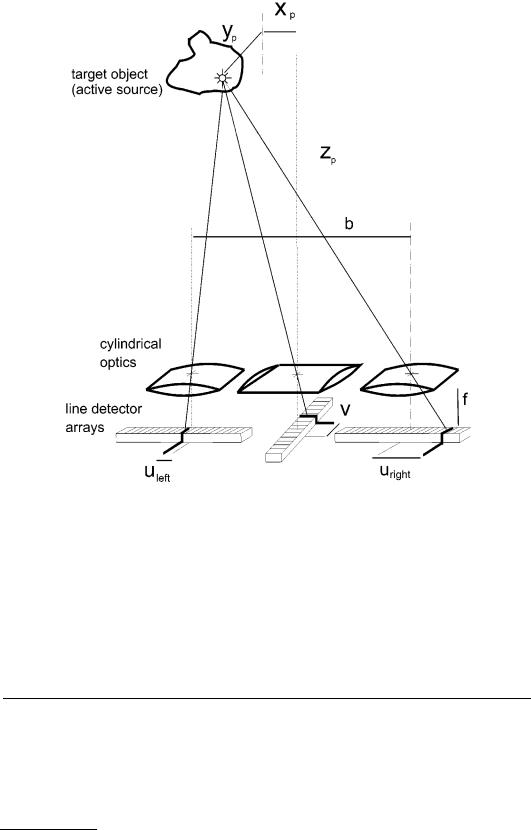
FIGURE 9.8 The OPTOTRAK position tracking system employs a novel arrangement of cylindrical optics and onedimensional detectors to triangulate the 3-D position of an infrared LED target. Up to 255 individual multiplexed targets can be tracked by the system.
implies an extreme sensitivity loss with distance, whereas optical triangulation has a more benign 1/R characteristic. This, to some extent, explains why the volume of measurement and accuracy of optical triangulation systems is generally much better than for magnetic systems.
9.4A Sampling of Commercial Ranging, Range Imaging, and Motion Tracking Products
Table 9.1 contains information collected from vendor literature. Be advised when comparing specifications that test conditions, standards, and interpretations can vary significantly. The specifications, therefore, should serve only as a rough guide.
© 1999 by CRC Press LLC

TABLE 9.1 Ranging, Range Imaging, and Position Tracking Products and Vendors
Class |
Trade Name |
Principle |
Features |
|
Contact |
|
|
|
|
|
|
Ranging |
MicroScribe-3DX |
Instrumented |
50 in. spherical work volume, |
Immersion Corp. |
|
(contact) |
|
arm |
0.3 mm accuracy |
(408) |
467-1900, |
|
|
|
|
info@immerse.com |
|
Ranging |
LASERVISION |
TOF, laser |
50 m range, 4.9 mm accuracy @ |
ZIRCON Corp., |
|
(noncontact) |
|
|
15 m, integrated electronic level |
(408) 866-8600 |
|
Range-Imaging |
HYSCAN |
Active |
40 mm depth of field, 70 mm |
Hymarc Ltd., |
|
(line scan) |
|
triangulation |
swath, 0.025 mm accuracy, |
(613) |
727-1584, |
|
|
laser |
10,000 points/s |
info@hymarc.com |
|
Range-Imaging |
TriCam |
Active |
120 mm depth of field, 60 mm |
Perceptron Inc., |
|
(line scan) |
|
triangulation |
swath, 0.05 mm accuracy |
(810) |
478-7710, |
|
|
laser |
|
inquiry@perceptron.com |
|
Range-Imaging |
ALTM 1020 |
TOF laser |
330-1000 m range, 15 cm |
Optech Inc., |
|
(line scan) |
|
time-interval |
accuracy, 20° swath |
(416) |
661-5904 |
Range-Imaging |
Rangecam 7000 |
Laser or strobe |
uses standard CCD camera and |
Range Vision Inc. |
|
(area scan) |
|
triangulation |
light plane projector |
(604) |
473-9411 |
Range-Imaging |
LASAR |
TOF, AM Lidar |
2–40 m range, 60 × 70° max field |
Perceptron Inc., |
|
(area scan) |
|
|
of view, 360,000 samples/s |
(810) |
478-7710 |
Position |
OPTOTRAK |
Active target |
up to 255 targets, submillimeter |
Northern Digital Inc., |
|
Tracking |
|
triangulation |
accuracy, 5000 3 DoF samples/s |
(519) |
884-5142 |
Position |
Flock of Birds |
Magnetic field |
up to 30 position/orientation |
Ascension Technology |
|
Tracking |
|
based |
targets, approx. 10 mm acuracy, |
Corp. (802) 860-6440 |
|
|
|
|
144 6-DoF samples/s |
|
|
|
|
|
|
|
|
References
1.R. Resnick and D. Halliday, Physics (Part 1). New York: John Wiley & Sons, 1966. 4.
2.P. J. Besl, Range imaging sensors. General Motors Research Publication, GMR-6090, General Motors Research Laboratories, Warren, MI, March, 1988.
3.R. Resnick and D. Halliday, Physics (Part 1). New York: John Wiley & Sons, 1966. 3.
4.D. F. McAllister (ed.), Stereo Computer Graphics and Other True 3D Technologies, Princeton, NJ: Princeton University Press, 1993. Ch. 4.
5.L. E. Kinsler and A. R. Frey, Fundamentals of Acoustics, 2nd. ed., New York: John Wiley & Sons, 1962, Chs. 9, 15.
6.W. Diedrich, Foundations of reading sonar, The In-Fisherman, April-May, 42-56, 1996.
7.E. B. Blood, Device for quantitatively measuring the relative position and orientation of two bodies in the presence of metals utilizing direct current magnetic fields, U.S. Patent 4,945,305, Jul. 31, 1990.
8.W. J. Steinway and C. R. Barrett, Development status of a stepped-frequency ground penetrating radar, in Underground and Obscured Object Imaging and Detection, SPIE Proceedings, Vol. 1942, Orlando, FL, April 1993, 34-43.
9.J. Borenstein, H. R. Everett, and L. Feng, Where am I? Sensors and Methods for Autonomous Mobile Robot Positioning, 1995 Edition. University of Michigan report for the United States Dept. of Energy Robotics Technology Development Program, Ann Arbor, MI, 1995. Ch. 3.
10.Hymarc Ltd., 1995. Product Information, Hyscan 3D Laser Digitizing Systems. Ottawa, Ontario, Canada.
11.Perceptron Inc., 1995. Product Information, TriCam Non-Contact Measurement Solutions. Farmington Hills, MI.
12.F. E. Goodwin, Frequency Modulated Laser Radar, U.S. Patent 4,830,486, May 16, 1989.
13.F. Blais, M. Rioux, and J.-A. Beraldin, Practical considerations for a design of a high precision 3D laser scanner system, SPIE Vol. 959, Optomechanical and Electro-Optical Design of Industrial Systems,
1988.
©1999 by CRC Press LLC

14.D. K. Barton, Radar System Analysis, Englewood Cliffs, NJ: Prentice-Hall, 1964. Ch. 4.
15.A. V. Jelalian, Laser Radar Systems, Artech House, 1992. Ch. 1.
16.E. S. Cameron, R. P. Srumski, and J. K. West, Lidar Scanning System, U.S. Patent 5,006,721, Apr. 9, 1991.
17.Acuity Research Inc., 1995. Product Information, Accurange 4000. Menlo Park, CA.
18.R. R. Clark, Scanning rangefinder with range to frequency conversion, U.S. Patent 5,309,212, May 3, 1994.
19.Northern Digital Inc., 1990. Product Literature, OPTOTRACK 3D Motion Measurement System, Waterloo, Ontario, Canada.
20.F. H. Raab, E. B. Blood, T. O. Steiner, and H. R. Jones, Magnetic position and orientation tracking system, IEEE Trans. Aerospace Electronic Systems, Vol. AES-15, No. 5, September 1979.
21.E. B. Blood, Device for quantitatively measuring the relative position and orientation of two bodies in the presence of metals utilizing direct current magnetic fields, U.S. Patent 4,945,305, July 31, 1990.
© 1999 by CRC Press LLC