

Figure 9.33 Digital implementation of Laplacian operator.
where
![]() is a constant. Equation(9.41)
can be interpreted as
is a constant. Equation(9.41)
can be interpreted as
![]()
In other words, we can simply use a subtractive linear combination of the blurred image and its Laplacian to restore the unblurred image. Reference to Fig. 9.33 gives
![]()
![]()
and
![]()
![]()
The Laplacian of the image function f(x,y) will then be
![]()
or
![]()


(a) (b) (c)
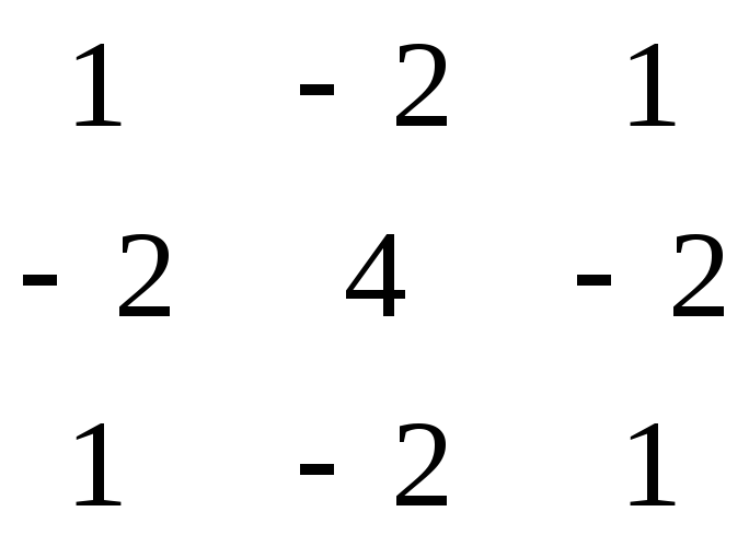
Figure 9.34 Laplacian masks.
If
both
![]() and
and![]() are
chosen to be unity,image
processing, we have
are
chosen to be unity,image
processing, we have
![]()
where
![]()
is the average of the four neighbors of the image point under consideration. Equations (9.47) and (9.48) can further be put in a form as the convolution of a mask (called a Laplacian mask) with the image function window

The
Laplacian mask can be used to detect lines, line ends, and points
over edges. By
convolution of an image with a Laplacian mask, we can obtain edges
sharpening without regard to edge direction. The mask shown in part
(b) of Fig. 9.34 is
obtained by adding the mask shown in part (a) to the result obtained
when part
(a) is rotated by 45°. The mask shown in part (c) is obtained by
subtracting the
mask in part (a), after it has been rotated by 45°, from twice the
mask shown in
part (a). The Laplacian of pixels at the edge is high, but it is not
as high as that at the noise point. This is because the edge is
directional, whereas for the noise point, both
![]() and
and![]() are
high. With this property in mind, the
are
high. With this property in mind, the
noise points can be distinguished from the edge pixels. Some other measures will be provided for the detection of edges only.
Algorithm 5. Nonlinear edge operators. Among the nonlinear edge operators are the Sobel operator, Kirsch operator, and Wallis operator.
Sobel operator: This operator is a 3 X 3 window centered at the point (j,k) as shown in Fig. 9.35. The intensity gradient at the point (j,k) is defined as either
![]()
or
![]()

Figure 9.35 a 3x3 window for edge detection.
Where sx and sy are respectively, computed from its neighbor according to
![]()
![]()
or the Sobel high-pass
weighting masks are, respectively
![]() and
and![]() for
computation of the horizontal and vertical components of the gradient
vector in the x and y direction at the center point 3X3 window inFig. 9.35
for
computation of the horizontal and vertical components of the gradient
vector in the x and y direction at the center point 3X3 window inFig. 9.35

and

Convolving these masks with an image f(x,y) over all the points on the image gives the gradient image. Figures 9.36 to 9.39 show the original images, the images comprising all the horizontal edge elements, those comprising all the vertical edge elements, as well as the complete images which combine all the edge elements responding to various directional masks.
Kirsh edge operator: Another 3x3 nonlinear edge enhancement algorithm was suggested by Kirsch (see Fig. 9.35). The subscripts of it made such that they are labeled in ascending order. Modulo 8 arithmetic in this computation. Then the enhancement value of the pixel is given as
![]()
where Si, and Ti are computed, respectively, from
|
(a) |
|
(b) |


Figure 9.36 Gradient image obtained by applying Sobel edge operator: (a) original image; (b) response of all horizontal edges; (c) response of all vertical edge elements; (d) response of all 45° edge elements; (e) response of all 135° edge elements; ff) response of all (sx + sy) edge elements; (g) response of (s45+s135) edge elements; (h) complete gradient image
|
(a) |
|
(b) |

