

Phedotikov / 1 / FreeEnergy_27.01.08 / !Информация / Free Energy Projects
.pdfFREE ENERGY PROJECTS 2
gaps ,the best insulated wire and sufficient length for the correct magnetic strength. You will need to construct it on a non magnetic frame to prevent magnetic losses. Also select a suitable prime mover to drive the unit. Whether a D.C. motor, Hydro Wheel or windmill. Using this setup means no relative motion between coils and the magnetic field and the disk will accelerate into the permanent magnet poles and slows down on the way out and therefore should result in a steady speed. The voltage is directly related to the change rate of the magnetic field and speed of the rotor. Amperage is related to how long the pole faces are in position with each other.
Liquid Piston Pump
The idea is credited to a Scottish inventor called Robert Stirling in 1816. The idea is that a fixed quantity of air is pushed between two chambers one hot and one cold. The resulting changes in air temperature and pressure can then be used to perform work. I have seen this little pump in many forms In the late sixty's I saw one on a television science program one made entirely of glass with ball bearings for the valves and heat from a from a spotlight to power the device. Another I have seen was made from metal piping and heat supplied from a lit gas jet to power the device. The one in the illustration can be made from cheap plastic irrigation water piping fittings and values from a cheap plastic hand liquid pump. The one thing common to all models is that all joints
PAGE 81 OF 91

FREE ENERGY PROJECTS 2
be air tight. The items you will need as in illustration or to make it a little easier you could use small irrigation or garden water fittings that come with threaded ends. It is then just a case of screwing them together. The flat valves could be pieces out of the liquid pump Two three or two litre empty plastic coke bottles with their tops .These will be the air chambers one for hot one for cold Construction The alignment is of as in the illustration. The illustration is pretty clear I believe and just to add to it, the following information may be of assistance to you Remove the tops from the coke bottles and drill a quarter inch hole in center of each top Cement with plastic putty or whatever you have available the tops in one side of a T Piece make sure that it cannot move and is air tight . You will need two of these , and when the unit is finished the plastic bottle will be screw into the glued plastic tops. Connect other pieces as in diagram. You may use what ever you can for valves but they should be light round and flat or even a glass marble fitted into a rounded drill hole in flat piece of plastic inserted or glued into a irrigation connection piece and most important they must only allow water to flow in one direction and block it from flowing backwards The other type of valve could be the same drilled hole but with a piece of flat rounded plastic resting on top of it placed on such a way that it cannot move sideways but can move freely upwards and downward. Priming the pump Place suction inlet into source of water and pour water into top of unit until level with second level piece under the plastic bottle tops. Water should now be flowing out of the outlet pipe when correct level is reached Place plastic bottles in position ,one bottle should be exposed to sunlight and the other kept as cool as possible. Improvements that could be worth trying are Put some black paint inside a plastic bottle and roll around until the inside surface is covered with the black paint. This will be the bottle exposed to the solar heat. The other could have a large tin can collar with a small hole in bottom of the can to allow the thread of plastic bottle to exit and be joined to rest of connections. This should have a water tight seal to prevent leakage. When properly sealed, add water to collar and natural evaportion will keep thre plastic bootle cooled. Or alternately use more connections so that the bottles could be stood right way up and the cooling bottle put into can from the top. How it works: The invention alternatively pulls up water through the bottom value and then pushes it through the top valve. When the air heats up in the hot air bottle pressure expands thus forcing the water in tube out . When the air is cooled down it contracts creating a vaccum that pulls water up through the bottom and so on. The unit should keep working until heat source is removed. You may need to experiment to make this unit work more efficiently. Possible use Although this is only a demo unit a bigger one could be built and used in a hydroponic garden for water cycling or for the cooling unit in the solar desalination unit described elsewhere.
PAGE 82 OF 91

FREE ENERGY PROJECTS 2
Wally Minto Temperature change wheel
In 1975 Wally Minto donated a design to the world. His unpatented wheel worked on a change of temperature as low as 3.5 degrees. Apparently if you handy with a welder you can build one too. You will need a selection of gasproof tanks of the same size and then weld them into a wheel shape. Each tank opposing each other should have a hollow tube connecting them together. Each tank should also have a low boiling point gas in them as well. Arrange on a axle so that only one or two tanks will me immersed in heated water (solar Perhaps) Operation The bottom gas tank is immersed in a tough of water solar heated or otherwise. The gas in the bottom is heated and the gas becomes lighter and flows to opposite tank where it cools down where it becomes heavier again. The heavier gas tank is then drawn down by gravity and the process begins again. The temp wheel rotates at slow speed but has high torque so step up gearing may give a higher speed output
For winter operation, a large heat collector buried under ground will supply the 3 and 1/2 degrees required to make it work during the winter.
In fact a bigger heat collector buried for winter use would be better along with a summer collector.
This Minto's motor will generate lots of power. If you need water or electricity this is the unit that could supply it.
PAGE 83 OF 91
FREE ENERGY PROJECTS 2
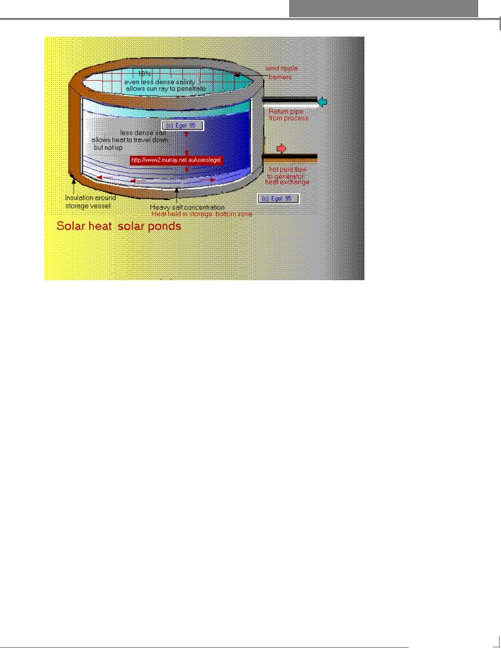
Solar Ponds
Those large areas of the planet covered by salt ponds may be yet be of some use after all. Work today is being carried on in Israel where they have the best location for work of this kind, that being the Dead Sea where they have built a power station using heat stored in this sea
. There are also other areas in the United States of America and even in Australia. Areas In rural Australia which are being destroyed by a salt may yet be made useful for energy production. These Ponds to be useful must have three differing zones of salt concentration not easy to obtain which work together to trap and store heat originating from the sun. The surface zone the lightest in salinity allows the heat to travel down but not upwards and also acts as buffer to the second zone. The second zone prevents heat from returning to the surface. The third zone with the greater concentration of salinity acts as thermal storage and readily absorbing the solar heat rays`. The weather pattern in the area has a great bearing on the effect of this heat storage pond where evaporation and wind patterns can completely destroy any heat storage capability The wind can cause the three zones to mix therefore destroying the heat thermal storage properties of the pond. Floating wind barriers have been introduced to reduce the ripple effect of the wind across many lake surfaces. Some solar ponds can have a
PAGE 84 OF 91

FREE ENERGY PROJECTS 2
temperature of 100 degree c in the lower zone, whilst having a considerable lower one on the top zone.. Brine is pumped from the pond at the correct level and passed through a heat exchanger and maybe a temperature phase changer and is put towards a number uses from power generation to desalination plants. Water from the top of lake could be used in the process for cooling as there is a temperature difference between the zones. Although a large surface is required for the collection of the solar energy ,I have noticed an effect when I was storing gherkins in large wooden barrels containing salt water. When the gherkins were removed and the brine was left to stand after a period of time in the sun there was always a cold top layer and a warmer bottom layer whenever I inserted my hand to drain them. I am sure this idea using a large wooden barrel or insulated container bottom and sides and connected to solar panel with water flowing to bottom layer could be used as a heat storage unit. This could also be improved by having a glass top to direct sunlight into bottom layer.
Increasing Electrical power
Method and Apparatus for increasing Electrical power Inventor Robert W.Alexander patent 3,913,004 Dated October 14 1975. This is an interesting patent in that it actually claims to produce more power than it uses. The Patent Abstract A form of rotating machine arranged in such a way as to convert a
PAGE 85 OF 91
FREE ENERGY PROJECTS 2
substantially constant input voltage into a substantially constant output voltage :,involving generally a rotor that revolves at substantially constant speed within a stator which comprises a transformer coil subjected to and having a primary motorised transformer winding and a secondary transformer generator winding , whereby transformed and generated power are synchronously combined as increased output power.
The illustration is not an accurate design of his design but meant to convey an experimental setup. Robert's design employed a four pole generator of which the petrol motor had been removed. He kept the stator field setup He unwound the armature coils and replaced them with two windings each windings occupied the same slots of the armature. He connected the ends of the first primary windings to a four pole commuter and brushes setup . I believe this could have been a series connection setup but am not sure. and the secondary coil winding to slip rings. This transformer had a ratio of 3 to 1 in the secondaries favour. The armature primary field and the stator coils were connected to a 48 volt power source (four batteries) When power was applied the unit acted like a Dc motor The commuter action reversing the armature poles and the alternating current being induced in the secondary winding along with the magnetism produced from the stator coils.
PAGE 86 OF 91

FREE ENERGY PROJECTS 2
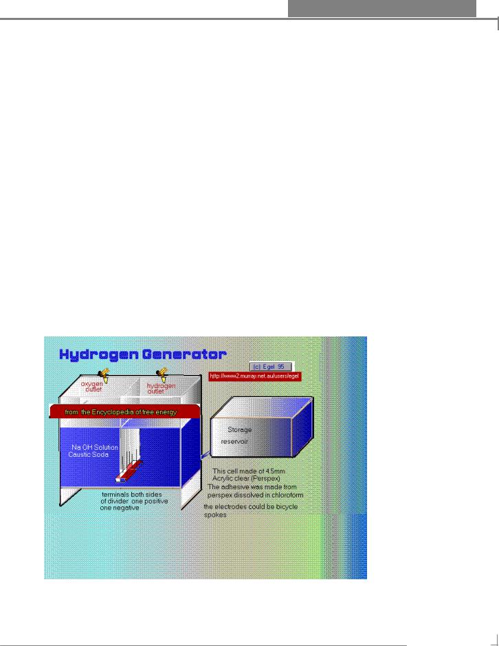
Hydrogen Fuel generator
When the word hydrogen is mentioned, most people have visions of a pre world war two air ship going up in flames over the United States. Most people think they saw explosions in the newsreel footage but what really happened, was it just burnt to pieces and burnt upwards as well. In the news services there have been claims of inventors making hydrogen from water economically. We shall see in time, if it can be bought forth by them. An automobile suitably modified could be made to run on hydrogen and that hydrogen could be made from the one thing that is in abundance now, sea water, if it could be done more efficiently than today. Getting hydrogen and oxygen is just a simple matter of putting two electrodes in water, keeping them apart and turning on a direct current power source of in excess of 2.5 volts. You should now see two electrode giving off bubbles the faster one is the hydrogen and the other is oxygen. Water that has a 30% caustic soda content could improve the generation
WARNING But be careful when dealing with caustic soda, it can leave a very nasty burn if splashed on your skin, Wash it off immediately upon contact Use safety protection gear rubber gloves and goggles you just can't be too careful when dealing with this substance.
If you don't want to chance it. my informant suggested using washing soda instead.
The colour illustration is something along the same lines as above, with some important differences. Two set of electrodes are mounted next to a perspex sheet one side for the hydrogen and the other for oxygen. The electrodes should be set at a height that the gases do not intermingle. By doing this there is formed two collection cells in the device. The water solution is able to pass underneath to both sides, and is filled from an opened topped reservoir set higher than the level used in the reaction chambers ,this is important in control of the gas pressure build up and prevention of an explosion. When electrical power is turned on gas flows from each set of electrodes and into the top of their individual cells. When gas builds up the water levels will drop and water is forced back into water reservoir. The levels will return to normal when gas is removed form the holding cells Gas can be extracted from taps at top of each cells. The electrodes could old carbon rods from spent batteries or iron nails or bicycle spokes. The more in each set of electrodes and closer the better will result in better gas production. The power source could be the brine battery as described in this book as long as voltage is more then 3 volts. A slight alteration could be to use a variable dc power
PAGE 87 OF 91

FREE ENERGY PROJECTS 2
pulse and find by experimentation the best resonance frequency for the gas production. The cells are made from about 4.5mm acrylic clear perspex and can be any size but roughly the same shape as in the illustration. The glue can be made by dissolving some of the perspex in chloroform. Other parts taps ect you should be able to obtain from a good scientific supply house. If you have proper tanks to store your gases they can be recombined in a fuel cell such as those used by NASA to give electricity and pure water at a later date.
Ionic Electrical Generator.
Here we have a new idea to generate electricity The forms we now have are Hydro electricity is clean but the water storage dams needed eventually silt up and beside they usually destroy our wilderness that are needed by our city residents to unwind. Nuclear Power has been with us for some time but has proved to have dangerous results and the waste storage is still a problem waiting to be solved. Solar and wind generators are not a twenty hour four proposition with out the costly storage devices. Coal based generators are only adding to our Green house gas problems. The idea here is generate electricity by means of the air pressure that surrounds all of us. The method has none of the problems associated with those methods described above and is renewable as well. Every one of us is familiar with the concept of the
PAGE 88 OF 91

FREE ENERGY PROJECTS 2
chimney. In this design Air is drawn from below into the chimney and up to the top where it is decomposed by Ionizing rays and then re absorbed into the atmosphere. Where air has been Ionized it creates a vaccum and draws more air into it. from below. This causes an air flow that could be utilized to turn a electrical turbine. In a design say with a dome of twenty metres surrounded with ionizing equipment on top and a air tube of 4 metres diameter through the centre , a turbine inserted in the middle would be subject to forces in excess of 120 tons To put things into perspective that is say equal to 1 square meter of water falling from height of over 120 metres. Of course the whole generator would have to be constructed in such a way than the Ionic rays would not present a health hazard to those nearby, although this should not be much of a challenge. The atmospheric ionization on one side gives rise to enormous pressure on the other. The electrical power is extracted by air turbines when these two pressure areas try to normalize. This is a imaginative idea that needs to be looked at seriously. Thanks to identity known only as the captain for this idea wherever you are.
Single Pole Generatorr
North Pole Generator Having a permanent magnet for the armature is relatively new idea and means no slip rings or commuter is needed to take the current and voltage off as in the case of using it as a generator To make a permanent magnet armature motor with one south and one north pole would mean a way would needed to be found to reverse the current and voltage flow to the field coils so that it could match the speed of the rotor at start up and in turn repel and attract the poles of the permanent magnet armature. Maybe a Hall field effect device to sense the magnetic pole type could be used to control the switching if you really wanted to go this way. Taking the centre armature permanent magnet idea one step further however and relying only on the magnetic repulsion effect, the following simply would only be needed to be
PAGE 89 OF 91

FREE ENERGY PROJECTS 2
done. You will need four strong bar magnets and place them at ninty degrees to one another, all with the same poles facing outwards With any permanent magnet design it is important the spacing between magnets is equal. Mount the four laminated bar and stator winding fields with the same winding configuration pattern facing the same direction and with one end facing outwards. The stator fields could also be mounted top down or bottom up instead of the flat position as displayed, as long as the electromagnet pole faces are the same direction in relation to the permanent magnet armature. The permanent magnets are mounted sandwich like, in the case of the flat bar fields as illustrated in design, between two non magnetic materials with a shaft mounted in the centre. Other ways would need to be done for other positions. To use as a generator spin the sandwich wheel by some means and pulsating power will be produced in the field winding subject to pole facing, rotor speed and magnetic strength and field windings. To use as a motor, a cross arm conductor mounted in the rotor centre and making contact intermittently with a fixed conductor to pulse power, this means really just opening and closing a current flow as no current reversal is required, as we are only interested in producing a repelling magnetic effect when magnet and field coils are in alignment with each other. Please keep in mind All the air gaps between poles and stator pole face should be kept to the closet spacing you can get. The stators should be made of steel laminate pieces. The coils should be wound with the best insulated wire you can get. With this design you are not limited to four permanent magnets and field coils but you could use more or less, as long as field coils and magnets matched each other and the conductor arm can supply the correct pulse sequence. You may like to check out a variation of this design by New Zealander Robert Adams who has made something like this but uses it as a combination motor and generator at the same time. With Power being returned to batteries running unit. He has a manual available Giving design details and performance data achieved so far Many claim to have built this creation and got it to work satisfactory using this information. A copy can be obtained from Nexus Magazine Australia for about $40 Australia Plus Postage overseas buyers may care to check first for the cost to them. The address is in the information section of this magnetic book.
PAGE 90 OF 91