

Phedotikov / 1 / FreeEnergy_27.01.08 / !Информация / Marinov
.pdfObservations of the Marinov Motor
Thomas E. Phipps, Jr.
908 South Busey Avenue
Urbana, Illinois 6180
It is verified that the Marinov motor works and that its torque magnitude roughly agrees with the theory given by Wesley(1). The existence of this device appears to refute the widely-held belief of physicists that the Lorentz force law suffices to describe all observable electromagnetic force manifestations.
Introduction
I confess to having had the popular (among physicists) view of Stefan Marinov as a buffoon adept primarily at self-advertising. That opinion I no longer hold, since I have been able by my own observations to confirm the operability of one of his inventions, a motor he called “Siberian Coliu.” [I follow Wesley(1) in calling it here simply the Marinov motor (MM).] Wesley has done a service to the physics community in clarifying, by means of a simple sketch (Fig. 1 of his accompanying paper(1)), just what the Marinov invention is. Fig. 1 of the present paper shows the same thing, but with sense of rotation corrected to agree with what has been observed empirically for the case in which the vertical members of the toroid are permanent magnets. It will be seen that the elements are starkly simple: A permanent magnet of roughly toroidal shape, entirely (?) enclosing its own magnetic (B-field) flux, is placed inside a conducting ring. If the magnet is held stationary in the laboratory and the ring is supported in bearings, then the ring will rotate continuously in the laboratory, provided direct current is brought into it through sliding contacts (brushes) situated in the vertical plane of the toroid. Alternatively (and more easily tested), if the central toroid, termed the “armature,” is suspended by a filament, as in a torsion balance, so that it is free to rotate, and the ring is held fixed in the laboratory with current leads attached to it adjacent to the vertical members of the armature, a measurable torque will be exerted on the suspended armature when current 2i is turned on (which then divides so that current i flows in the upper half of the ring and i in the lower half). This torque, which is easily measured, causes the armature to turn up to 90 degrees.
The extreme simplicity of this conception must be emphasized, and also the bizarre nature of the force responsible for the observed unidirectional torque. Everything is electrically neutral, so there is no E-field to speak of; and magnetic flux in the case of an ideal toroid is entirely confined within the toroid, so that none is present at the position of the current; hence Y × % or L × % should vanish. In this idealized case the Lorentz force law would predict zero force and zero torque. Of course, in any practical realization of the concept there must be flux leakage. But it is at least surprising that a seemingly second-order phenomenon, weak and random in character, such as flux leakage, in all cases thus far investigated by at least three independent US observers (T. Ligon, J. D. Kooistra, and myself) should consistently yield strong torques. Also, if departure from ideality were driving the motor, enhanced departure should drive it better; but it doesn’t.
The question of torque-sense seems empirically to depend on construction details of the magnetic toroid. We shall not try to resolve all complexities here, but offer a simple rule-of-thumb.
APEIRON Vol. 5 Nr.3-4, July-October 1998 |
Page 193 |
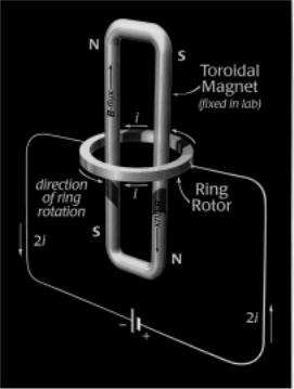
Fig. 1. Schematic of one simple form of Marinov motor. The indicated sense of ring rotation agrees with what has been observed for the case in which the vertical members of the toroid are permanent magnets.
Referring to our Fig. 1, current flows clockwise (CW) [as seen from above] in the near half of the horizontal ring, and counterclockwise (CCW) in the far half. The B-flux is largely contained within the toroid, and circulates CW in the view shown in Fig. 1. Maxwell’s equations, incidentally, provide no means, without cutting into the toroid, to say which way the flux goes. But we may consider ourselves possessed of this information as a result of having constructed the toroid from magnetic parts, such as bar magnets. So, since the B-flux lines are contained and in any case lie in a plane normal to the ring plane, why does the ring turn always one way rather than the other?
A clue to “handedness” comes from recalling the original Ampère description of a permanent magnet in terms of tiny “current whorls,” which in modern parlance would be aligned electron spins. If we slice horizontally across a vertical arm of the toroid at the level of the ring, in thought we expose a planar assemblage of these current whorls, which are considered to cancel each other internally and leave uncompensated only a surface polarization or “magnetization current,” which is treated in Maxwell’s equations in the same way as a real current. The important thing to note is that this virtual surface current is unidirectional and has a definite sense determined by the sense of the flux internal to the magnet. If the flux vector points up, as in the left side of the toroid shown in Fig. 1, then by the right-hand rule the sense of circulation of surface current in that portion of the magnet is CCW, as seen from above. (We treat it as a conventional plus current, as if it were real current in a solenoid.) So here, finally, is something about the physics that favors one sense of torque acting in the horizontal plane over the other. But note that none of this is obvious to the eye of the beholder. We have had to ascribe a sense to flux, not visible, and a sense to surface magnetization current, also not visible.
In the older electrodynamics of Wilhelm Weber(2), which featured direct action-at-a-distance of one electrical point charge on another, the “magnetization current” circulating around the surface of
Page 194 |
APEIRON Vol. 5 Nr. 3-4, July-October 1998 |
the permanent magnet nearest the ring would presumably be treated in the same way as real charge in motion. It would induce an action on the real currents in the adjacent ring portions that would lead to exertion of a ponderomotive force on the ring. An alternative (essentially equivalent) approach employs the original Ampère force law between current elements(3). Although quantitative calculations using this law would be complicated, it does furnish a simple rule of thumb by which sense of rotation of the Marinov motor can generally be inferred: Adjacent (side by side) parallel current elements mutually attract and anti-parallel elements repel. This rule also works for the Lorentz force law, under the same fiction that surface magnetization (polarization) currents are real ones. Applying this to components of virtual surface current and to components of real ring current in closest mutual proximity usually gives the correct sense of rotation without need for integrations. (Thus, considering the left toroid member of Fig. 1, with B-flux up, the virtual surface current on the toroid adjacent to the ring is CCW; so it is parallel to the far ring current and anti-parallel to the near ring current. Hence the far part of the ring is attracted and the near part repelled. Both these actions produce CCW rotation of the ring, as observed.) This is only an empirical rule. Unfortunately it does not distinguish among the Ampère, Lorentz and other classical force laws. For that, both further experiments and more exact theoretical calculations are needed.
Wesley(1) analyzes the situation in more modern terms of vector potential A, related to B-field by % = Ñ ´ $ . Because of its normalization or gauge problems this potential has been supposed, since the days of Heaviside, to be not physically “real.” But this is hard to accept in view of more recent evidence such as the celebrated Aharonov-Bohm effect (4). (Comparing with our Fig. 1, it will be seen that the A-B experiment is just a one-solenoid version of a micro “Marinov motor,” with encirclement by the two “parts” of a single electron playing the role of the ring current.) Wesley (1) simply defines A as the integral of current density divided by separation distance from the test element (detector)—thereby fixing “gauge” and unambiguously determining both A and B. This seems a reasonable solution, though hardly respectful of those physical theorists who have founded gauge theory on a different definition. Ultimately, some other mathematical language will doubtless be found to describe what is happening in the Marinov motor; meanwhile the vector potential appears to suffice.
Both Marinov and Wesley noted this sufficiency of the A-potential. In accepted electromagnetic theory it is established doctrine that only the E-field does non-vanishing work on charge, and that E- field is related to the potentials by ( = -ÑF - ∂$ ∂ FW . Such a formulation does not suffice to explain the observed torque in the Marinov motor. But these investigators noticed that a slight formal modification of this definition, replacing the partial time derivative with a total one,
|
E = -ÑF - |
1 |
|
dA |
, |
(1) |
|
|
|
||||
|
|
c dt |
×Ñ6 , an extra |
|||
introduces via the convective part of the total time derivative, d / dt = ∂ /∂ t + 1vd |
||||||
“convective” force term that can be associated with motional induction, |
|
|||||
)FRQYHFWLRQ |
= -1T F60YG ×Ñ5$ , |
(2a) |
||||
PRWLRQDO LQGXFWLRQ
which is just right to account for the observed torque. This is true because the A-vector is not confined within the magnet (or solenoid) structure but describes what Wesley terms an “ A-field” existing outside the magnet and in contact with the conventional plus ring current, which has velocity v with respect to the laboratory (or with respect to the magnetic source of the A potential, as Wesley conceptualizes it).
APEIRON Vol. 5 Nr.3-4, July-October 1998 |
Page 195 |
We consider the convection to be effected by an A-field detector of velocity YG comoving with the actual (electronic) charge carriers constituting the current; i.e., anti-parallel to conventional plus current, so that YG = -Y . In the relation qv = ids, both v and ds point in the direction of conventional plus current flow, so q and i are to be treated as positive quantities. (Our choice to use conventional plus current in describing the “sink” current is demanded by consistency with our similar choice in describing the “source” virtual current that determines the sign of A. The opposite choice, to consider negative electron currents at both source and sink, would change the signs of both q and A, without affecting YG , so that, by Eq. (2a), the observable torque sense would not change.) Eliminating the c-factor by suitable choice of units, we can write our new force in a form more useful for calculations,
) = -T YG ×Ñ $ = T Y ×Ñ $ = L GV×Ñ $ . |
(2b) |
This “new” force term, by the way, was actually tacitly employed by Dirac in formulating his electron theory, as has been pointed out elsewhere(5).
As a footnote, I may add that a justification for using the total time derivative instead of the partial one, in all equations of electromagnetic (EM) theory, was given by me in a 1986 book(6). There it was shown that Heinrich Hertz’s first-order (Galilean) invariant reformulation of Maxwell’s equations(7) amounted to just this very replacement, ∂ /∂ t ® d / dt , plus a trivial adjustment of the current source term to allow for Galilean velocity addition. I also pointed out that Galilean (inertial transformation) invariance at first order requires the same replacement to be made in the treatment of the vector potential. [See Eq. (4.45), p. 134 of Ref. 6, or p.185. The convective velocity parameter YG was there identified as “velocity with respect to the observer’s inertial system of whatever detection instrument gives operational meaning to F $ .” This fits the present case, in which the A produced by the totality of magnetization current in the armature is measured by a hypothetical “instrument” comoving and collocated with a physical current-carrying point charge within the ring.
That is the meaning of “convection.”] Thus first-order invariance demands that all time derivatives of both field quantities and potentials be of the total, rather than partial, variety. Such invariance embodies(8) first-order “relativity,” although it violates “spacetime symmetry” (since d/dt is not mathematically symmetrical with partial space derivatives).
I confess that this 1986 recognition of the need for total time derivatives was a purely theoretical observation on my part and that I had no inkling of any practical implications for observable effects, nor of the work of Marinov or Wesley in this regard. The superiority of invariant formulations should need no “selling” to physicists or mathematicians. What apparently needs selling is the almost self-evident proposition that first-order force effects are the ones most plainly visible in the laboratory, and that first-order invariance requirements—entirely overlooked by physicists in favor of going at once to covariance based on second-order ( Y F ) considerations—must be met first in order to describe properly (i.e., in conformity with a Galilean relativity principle) all physical forces observable at first order in inertial systems. Thus I repeat one of my litanies(6), that each order of approximation constitutes a “physics of its own,” answerable to its own invariance requirements… and that first-order approximations take preemptive precedence. In short, valid theory must be compatible with a development by successive orders of approximation, starting with the first.
The new force that drives the Marinov motor could be called the Marinov or the Wesley force, or it could with equal justice and accuracy be called the Maxwell-Einstein first-order-mistake force. The mistake was in failing to demand rigorous formal invariance of the equations of electromagnetism at first order. Einstein, in particular, should have paid more attention to Hertz(7), by actually
Page 196 |
APEIRON Vol. 5 Nr. 3-4, July-October 1998 |
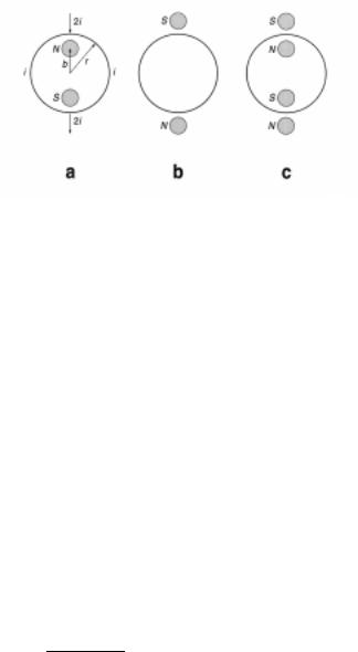
Fig. 2. Schematics (a) of Wesley’s version of the Marinov motor (top view of ring rotor and solenoids, with current direction reversed, brush contact locations indicated), (b) of a modification in which solenoids, with reversed polarities, are situated outside the ring, (c) superposition of cases (a) and (b).
trying to understand him, instead of sweeping him under the carpet in the typical physicist’s way by reference(9) to “Maxwell-Hertz equations.” The fact is that Maxwell’s equations are spacetime symmetrical, whereas Hertz’s are not (as we said, alongside partial space derivatives, they contain total time derivatives rather than partial ones … although Hertz’s execrable non-vector notation admittedly hid this from the hasty eye). So, there are no Maxwell-Hertz equations and Einstein’s “Max- well-Hertz” reference was an oxymoron. But no physicist, even today, gets the joke, because all are as heedless of Hertz as was Einstein. To say that there is no first-order invariance is to say that there is no first-order relativity … and that is contrary to nineteenth-century empirical evidence of Mascart(10) and others, who showed first-order relativity to be an experimental fact.
In this paper we shall first apply the basic theoretical torque formula obtained by Wesley(1), without repeating his derivation of that result. The purpose will be to suggest some of the range of variations possible in the basic design of the resulting new class of motors. Then some experiments I did to test the torque formula will be described. No attempt will be made here to analyze specific embodiments of the Marinov motor—but any reader with engineering leanings will be able to fill-in that part of the story.
Torque Formulas
For a current-carrying ring of radius r surrounding two oppositely oriented (N and S poles up) infinite-length “solenoids,” each of infinitesimal radius and cross-sectional area δ$ , having centers (located azimuthally on the same ring diameter as that at which current is introduced to and taken out of the ring) at radii ±E , Wesley has derived(1) the formula for the infinitesimal increment of ring-torque magnitude corresponding to δ$
δ7E<U = |
%Rδ$LDPSEU |
|
π U − E . |
(3) |
Here lengths are expressed in cm and %R , the field internal to the solenoids, in gauss; LDPS is the DC in amps flowing in either half of the ring, total current in the external circuit being LDPS . The factor of 10 converts abamps to amps, yielding the torque in dyne-cm. (To convert to practical US units of torque, foot-pounds, multiply torque in dyne-cm by 7.3757 × − .) The torque is assumed to result from ponderomotive force applied to the ring at radius r. The geometry in plan view is sketched in our Fig. 2(a).
For purposes of analysis, Wesley considered solenoids. In my limited experience, it is possible that real solenoids, even when they contain core materials of high permeability μ , do not perform in
APEIRON Vol. 5 Nr.3-4, July-October 1998 |
Page 197 |
accordance with Eq. (3), but may possibly do so if %R is replaced by the (oersted) H-field ( + = %R μ ). There being as yet insufficient evidence on this subject, I leave that speculation to stand simply as a warning against unthinking interchanges of real solenoids (electromagnets) and permanent magnets, and conclude with the remark that empirical evidence on rotation sense in regard to armatures made from combinations of permanent magnets and magnetizable iron can be summed up in the rule of thumb stated in the Introduction. However, this rule must be applied exclusively to the permanent magnet portions of the magnetic circuit (toroid). Any portions that contain only externally induced flux can apparently be ignored. The situation, not unlike that for railguns,(11) must be considered presently unsatisfactory and in need of further investigation and clarification. If the ring is fixed, the torque on the inner structure (solenoids or magnets, considered rigidly connected) is opposite in sense to that on the ring, and Eq. (3) must be modified (viz., multiplied by b/r) to account for the smaller radius of force application. (It is forces, not torques, that obey Newton’s third law.)
We obtain a m ore revealing form of the torque formula by letting E = U − |
U , where |
U will |
|||||||||||||||
be considered small, U << U . Eq. (3) can then be written |
|
|
|
|
|
|
|||||||||||
|
δ7E<U |
|
E |
|
U − U |
|
|
U |
|
U |
|
|
|||||
|
|
|
|
= U |
|
|
= U |
|
|
|
= |
|
|
− |
|
. |
(4) |
|
& δ$ |
U − E |
|
− 0U − |
U5 |
|
U − U |
||||||||||
|
|
|
U |
|
U |
|
|
|
|
||||||||
This form shows the importance of proximity of the solenoids to the ring: At first order torque is inversely proportional to the separation distance U . The parameter appearing here is C = %RLDPS π , a combination that shows equivalent torque improvement to result from pro-
portional increase of either %R or LDPS .
Observe that the formula in Eq. (3) is symmetrical in b and r, except for a sign change. This
means that if we cancel the sign change by interchanging N and S poles of the “solenoids” we can place such flux-reversed solenoids outside the ring in the configuration shown in Fig. 2(b), and use the interchanged formula
δ7E >U |
|
E |
|
|||
|
|
|
= U |
|
, |
(5) |
& δ$ |
|
|||||
|
E −U |
|
||||
where E formally replaces b. For a symmetrical superposition of the two cases just considered,
illustrated in Fig. 2(c), letting E = U − |
U , as before, and E = U + |
U , we obtain by adding the sepa- |
||||||||||||||||||||||||
rate torques a total torque |
|
|
δ7E >U |
|
|
|
|
|
|
|
|
|
|
|
|
|
||||||||||
|
δ7WRW |
|
|
|
|
δ7E<U |
|
|
|
|
|
|
|
|
|
|
|
|
|
|
|
|||||
|
|
|
|
= |
|
|
|
|
+ |
|
|
|
|
|
|
|
|
|
|
|
|
|
|
|
|
|
|
& δ$ |
& |
δ$ |
|
δ$ |
|
|
|
|
|
|
|
|
|
|
|
|
|
|
|||||||
|
|
|
|
|
|
|
|
|
|
|
|
U |
|
0 |
U5 |
|
|
. |
|
|||||||
|
|
|
|
|
|
|
|
U − |
|
U |
|
|
U + |
|
U |
|
|
|
(6) |
|||||||
|
|
|
|
= U |
|
|
|
|
|
|
+ |
|
|
|
= |
|
|
− |
|
|
|
|
|
|
||
|
|
|
|
|
|
|
− U5 |
0U + U |
5 |
|
|
U |
− 0 |
U5 |
|
|
||||||||||
|
|
|
|
|
U − 0U |
|
|
− U |
U |
|
|
|
||||||||||||||
In addition to doubling the torque with twice as many solenoids, it will be observed that the departures from U behavior in (6) occur at second order, rather than first order, as in Eq. (4). This results from the higher order of symmetry in Fig. 2(c), as compared with 2(a,b). Since Wesley’s Gedanken solenoids extend vertically to ±∞ , we can imagine the connections interchanged “at infinity,” so that what is portrayed in Fig. 2(c) may be interpreted as two pairs of permanent magnet toroids (each obtained, e.g., by clinging-together two elongated U-shaped magnets), one encircling the upper portion of the ring shown in the figure and the other encircling the lower. Because of the importance of proximity considerations, already noted, what happens near “infinity” is not impor-
Page 198 |
APEIRON Vol. 5 Nr. 3-4, July-October 1998 |

Fig. 3. Variant of Fig. 2(a) in which the magnet armature vertical plane is inclined at azimuthal angle ϕ to the
ring diameter containing current leads to the ring rotor.
tant; and in fact the vertical extension of the magnets represented by solenoids (judging from empirical evidence) can be safely curtailed … although no theoretical attempt is made here to quantify the penalty for vertical truncation of magnets. (This has been done elsewhere(12).)
In summary of what we have learned so far: Proximity conduces to maximum torque, and the placement of extra magnets (“solenoids”) in close proximity to the ring can enhance torque. Similarly, it is easily shown that placing extra “rings” in a vertical stack above one another, will propor-
tionally enhance torque, all other things being equal. Similarly, wiring half-rings in series can be done in such a way(12,14) as to double torque. By such means it is anticipated that performance com-
parable with existing motor types may possibly be attainable(12).
Analysis for Arbitrary Magnet Cross Section Shapes
By integrating the force formula (2b), Wesley obtains a formula(1) that can be written (apart from
a difference of sign) as |
|
δF1φ (0)210 / iamp 7 = I0π / 2 1ds ×Ñ6 Aφ = I0π /2 2∂Aφ / ∂φ7dφ = Aφ (π / 2) - Aφ (0) , |
(7a) |
for force on one quadrant of the ring that includes the range of azimuthal angles φ between 0 and
π , exerted by the A-potential produced by the virtual surface currents flowing on the two sole-
noids. (All angles are in radians.) Here, as Wesley shows, |
- E 7 VLQφ |
|
|
|
|||
$φ 1φ6 = 3 &δ$ LDPS 8 |
|
E2U |
" |
. |
(7b) |
||
+ E 7 |
- U E VLQ |
||||||
! |
$ |
|
|
||||
|
2U |
φ# |
|
||||
The signs of current in the four quadrants being favorable to force reinforcement, he gets for the case of four quadrants a result four times greater,
δ)φ = 3 LDPS 8 |
|
$φ π - $φ |
|
, |
(8) |
|
|
for total azimuthal force on the ring produced by action of the solenoidal A-vector potential in the geometry of Fig. 2(a). When multiplied by the torque-arm r, this yields [since $φ = ] the
torque formula of Eq. (3), above.
We need to consider the more general case of arbitrary azimuthal offset angle ϕ , in order to assess the contribution to force on the ring of a pair of oppositely-oriented solenoids, such that one is
APEIRON Vol. 5 Nr.3-4, July-October 1998 |
Page 199 |
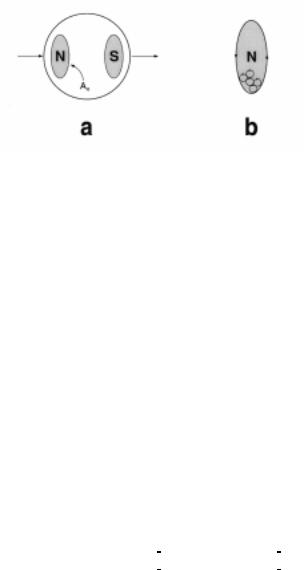
Fig. 4. (a) Variant of Fig. 2(a) in which armature magnets of opposite polarity have finite cross-sectional areas Ao of arbitrary shape. (b) Detail of one pole (cross section of area Ao ) showing hypothetical Am-
pèrian current loops that cancel internally and produce a virtual surface current circulating CCW for N pole, as seen from above. Each small loop may be considered to enclose a B-flux line. Conventional plus current is assumed.
located at arbitrary position 1E ϕ 6 and the other symmetrically across from it in the opposite quadrant at 1E ϕ + π 6 . Wesley’s result is easily generalized to handle this. The geometry in question is
sketched in Fig. 3. The case E < U is treated. We consider the ring current to be led in at point A and out at point E. Offset from this by an azimuthal angle ϕ is the line BF on which lie the centers of
the infinitesimal solenoids, each at radial distance b from the center point O. For analysis, we construct also the line CG, offset by the same angle ϕ on the other side of the inter-solenoid line.
By rough qualitative considerations involving the directions of current flow in the ring vs. surface current flow on the closest part of the adjacent solenoid (applying the Ampère rule for sense of rotation), it is easily seen that the force on the ring is CW in Fig. 3 along arcs BC and FG, and CCW along arcs AB and EF. Moreover, it is clear from symmetry about the line BF that the force on BC cancels the force on AB; likewise the force on EF cancels the force on FG. So, we can forget about the arcs AC and EG and just concern ourselves with the remaining arcs, CE and AG. Referring to Wesley’s geometry(1) (his Fig. 2), we see that the arc BD in our Fig. 3 corresponds to the quadrant he analyzed, so all we have to do is take four times the result of integrating over arc CD. Wesley defines his general azimuthal angle φ as increasing CCW from the azimuth line OD, the normal to
the inter-solenoid line. Thus the integral over the arc CD goes from φ = to φ = π − ϕ , so that for this quadrant
δ) φ = −3LDPS 8 |
|
$φ π − ϕ − $φ |
|
= −3LDPS 8 |
$φ 1π − ϕ 6 . |
(9a) |
|
|
The minus sign results from the fact that current, as represented in Fig. 3, flows CW along arc CD, oppositely to the direction of positive increase of φ . Hence the net ring torque is negative or
CW. As in Wesley’s special case, Eq. (8), the result for four quadrants is easily shown to be four times the single-quadrant value,
δ)φ = δ) φ . |
(9b) |
In going from force to torque, some care must be taken. The torque on the ring as rotor is not just the negative of torque on the solenoids as rotor, for the reason that Newton’s third law, as previ-
ously noted, does not apply to torques. Let us address first the case of torque on the ring as rotor. Since VLQπ − ϕ = FRVϕ , Eqs. (7b) and (9) yield for total force on the ring
Page 200 |
APEIRON Vol. 5 Nr. 3-4, July-October 1998 |
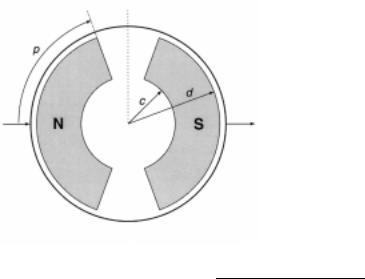
Fig. 5. Variant of Fig. 4(a) in which magnets have “parenthesis” cross sectional shape.
δ)φ ϕ |
= I U E ϕ ≡ |
|
E2U |
− E 7 FRVϕ |
|
||||
|
|
|
|
+ E 7 |
|
" |
. |
(10) |
|
& |
δ$ |
|
|||||||
|
|
|
! |
|
$ |
|
|
||
|
|
|
|
2U |
− U E |
FRV ϕ # |
|
||
We can forget about signs and treat LDPS as signless, if we deduce rotation sense by the Ampère rule previously stated. The ring torque is simply δ7ULQJ ϕ = Uδ)φ ϕ .
Suppose our stator consists of a pair of permanent magnets of arbitrarily-shaped cross-section, indicated by the region designated $R in Fig. 4(a). A magnet of opposite polarity and of shape that mirror images $R by reflection in the origin point at the center of the surrounding ring is presumed to be present. We ask, what is the torque exerted by this fixed magnet pair on the ring? To answer this, we have only to add up (integrate) the incremental torque contributions from each of Wesley’s infinitesimal solenoids over the whole area $R , of whatever shape. For Fig. 4(b) shows that by the original Ampère construction the small solenoid currents cancel on the interior of region $R and leave only a surface current circulating on the boundary of the region. It is this virtual surface current that we have been considering to act on the ring via its vector potential. But, by linear superposition, the torque action of the infinitesimal solenoids can equally well be calculated by simple addition (integration). The shape of the infinitesimal areas being inconsequential, we shall suppose that δ$ = EGEGϕ , a form adapted to the use of polar coordinates relative to the ring center. Then the
total torque on the ring rotor due to magnets of the arbitrary shape $R is |
|
||
Tring = r II δFφ (ϕ ) = Cr II f (r,b,ϕ )δA = Cr IIbf (r,b,ϕ)dbdϕ , |
(11) |
||
Ao |
Ao |
Ao |
|
where I U E ϕ is the function given in Eq. (10).
By contrast, if the ring is held fixed in the lab and the inner permanent magnet rigid structure, having our arbitrary shape $R , together with its image magnet of opposite polarity, is the rotor, then the torque on this magnet rotor or motor “armature” is the sum of the individual torques for “sole-
noids” situated at various b-values; viz., |
|
|
Tmagnets = II bδFφ (ϕ )δA = CII b2 f (r,b,ϕ )dbdϕ . |
(12) |
|
Ao |
Ao |
|
APEIRON Vol. 5 Nr.3-4, July-October 1998 |
Page 201 |
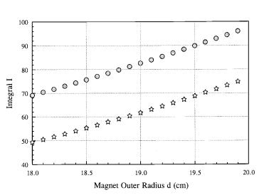
Fig. 6. Calculated value of normalized integral I for the case of ring rotor [upper curve, Eq. (11)] and ring stator [lower curve, Eq. (13)], for variable clearance parameter (outer radius) d.
( I = Tmagnets / 2C .)
We are fortunate in both cases (11) and (12) that the integrals can be evaluated in closed form for a sufficiently simple boundary shape of $R .
Thus if “parenthesis shaped” magnets of the sort shown in Fig. 5 are employed, the integral (12) over half the area $R of one member of the symmetrical pair of oppositely-oriented magnets in the ring-stator case takes the form
T |
d |
p |
(13) |
= CI = C b2 db |
f (r,b,ϕ )dϕ , |
||
half magnets |
Ic |
I0 |
|
|
|
where ϕ is half the angle that either magnet subtends at the center of the ring, and the material extends radially from c to d. Here, ϕ is in radians and c,d in cm. It happens that the double integrals in both Eq. (11) and Eq. (13) can be evaluated exactly. Note that Eq. (11) refers to the case of stationary magnets and ring rotor, whereas Eqs. (12) and (13) refer to the case of rotating magnets and ring stator. In the latter case the total torque on all magnet portions is simply twice the above result. Expressed in foot-pounds, this is
7 |
= × 7 |
× × − (ft.-lb.) . |
(14) |
PDJQHWV |
KDOI PDJQHWV |
|
|
Here & = %RLDPS π , with %R in gauss and LDPS the magnitude of the DC amperes flowing in
each half of the ring stator.
The double integral I in Eq. (13), or its counterpart [with integration from 0 to ϕ] in Eq. (11), is readily evaluated by any of several computer algebra programs, but the expressions are too long to reproduce here. (I used and highly recommend the user-friendly program DERIVE.) Putting in various numerical values to explore parameter sensitivity, we find the following qualitative results:
1)There is considerable sensitivity to the magnet outer radius d, which should be as near to r as feasible. The difference U − G represents the clearance between rotor and stator, which is ad-
vantageously made small. Fig. 6 shows the value of the integral I in Eq. (13) as a function of d for r = 20 cm, p = 45 degrees (expressed in radians, always, but we omit further mention of that), c = 8 cm. The figure is drawn to show both cases discussed above, the stationary ring case of Eqs. (12) and (13) [lower curve, open stars], and the stationary magnet case of Eq. (11) [upper curve, shaded circles]. The difference is seen to be 25% or more in favor of the ring rotor case.
Page 202 |
APEIRON Vol. 5 Nr. 3-4, July-October 1998 |