

Phedotikov / 1 / FreeEnergy_27.01.08 / !Информация / Marinov
.pdfFig. 8. Same as Fig. 6 for variable azimuthal angular half-width of magnet p.
The reason is that much of the torque in the ring stator case is exerted inefficiently on magnet portions at small radii (small torque lever-arm).
(2) Torque is rather insensitive to the value of c, which determines the magnet width, 0G − F5 , at the
smaller values of c, but falls off drastically if the magnet is made too narrow—in this case by increasing c beyond about 10 cm, as shown in Fig. 7. That figure assumes values r = 20 cm, p = 45 degrees, d = 19.0 cm, for the other parameters. This is a rather wide (1-cm) gap, but decreasing it does not alter the qualitative comparison of the ring-rotor and ring-stator cases (shown with the same meanings of stars and circles as in Fig. 6).
(3)The significance of the magnet azimuthal limit p is indicated in Fig. 8. This shows for r = 20 cm and d = 19.0 cm the effect of p-variation for our two cases, ring-rotor [upper curve, shaded circles] and ring-stator [lower curve, open stars]. The other parameter value assumed in this figure is c = 8 cm. Evidently, subtended half-angles in excess of 45-50 degrees yield comparatively little torque improvement, but decreases below about 30 degrees are costly.
All these results presume infinite-length magnets or solenoids. Formulas describing the effect of magnet truncation are given elsewhere(12). So much for an overview of the theoretical side. We turn now to the matter of empirical verification.
Torsion Balance Measurement of Torque
The writer is not the first observer in this country to confirm the existence of nonzero torque in the Marinov motor. As reported by Kooistra(13), Tom Ligon was the first to recognize that an easy
way to test the concept is to suspend a toroidal magnet “armature” shaped somewhat as in Fig. 1 of Wesley’s report(1), within a horizontal copper ring, fixed in the lab, to which current leads are attached. This eliminates the need for brushes, and emulates one very practical brushless motor design (which, however, requires periodic DC polarity reversals). Ligon observed vigorous turning of the armature up to almost 90 degrees when strong DC was put through the ring. At 90 degrees there is a torque null, and beyond that a counter-torque.
The approach reported here was patterned on Ligon’s. In order to make semi-quantitative measurements, I used a torsion balance, sketched in Fig. 9, wherein a horizontal wheel marked in twodegree increments around its rim, mounted on a vertical shaft held in bearings, could be rotated
APEIRON Vol. 5 Nr.3-4, July-October 1998 |
Page 203 |
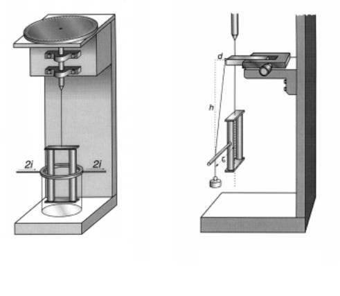
Fig. 9. Schematic of torsion balance used in presentlyreported torque measurements.
Fig. 10. Schematic of balance calibration method.
through a measured azimuthal angle to compensate any torque applied to a suspension fiber coaxial with the shaft. Thus by twisting the wheel the armature could be returned to its initial azimuth (null method). This was judged by observing the return to a fiducial position about ten feet away of a diode laser spot reflected from a small mirror (not shown) affixed to the armature.
After some false starts a suitable suspension fiber was found in a 5-inch length of 0.005-inch (127-micron) diameter tungsten wire. The ring was a copper gasket ring of thickness 0.21 cm, conductor width of 0.6 cm, and mean radius r = 2.118 cm, to which heavy leads of insulated #12 stranded copper wire were soldered at opposite ends of a diameter. These led straight out horizontally on each side for about 15 cm. (The lead dressing was not found to have any appreciable effect.) The armature, suspended centrally within the ring, consisted of two oppositely-oriented vertical Alnico cylinder magnets, each 5 inches long and 3/8-inch in diameter, bridged at top and bottom by small rectangular pieces of soft iron. The vertical members were aligned in the vertical plane containing the ring diameter where current was led in and out [like the configuration shown in Fig. 1, but with reversed current direction.] The separation of the centers of the two cylinder magnets was about 2.38 cm; hence the magnet radius parameter b had a value of 1.19 cm. This implied a clearance parameter U = U − E = 0.928 cm, which is quite large (i.e., unfavorable to high torque). Measurement with an AML GM1 gaussmeter, using a Hall effect transverse probe of about 1-mm thickness inserted between two of the cylinder magnets, indicated an internal magnetic field of about %R = 2300 gauss.
Page 204 |
APEIRON Vol. 5 Nr. 3-4, July-October 1998 |
Current was provided by a Hewlett-Packard 100-amp DC power supply (Harrison 6260A). Values of the ring current LDPS up to 10 amps (20 amps in the external circuit) were used. For small
angles approximately linear dependence on ring current of wheel angle θ REV required to compen-
sate torque on the armature was observed. The findings can be summed up in the empirical formula
θ REV |
= 10.40 to 10.61 deg./amp, |
(15) |
|
||
LDPS |
|
|
with an average of about 10.5 degrees of fiber twist per ampere of DC flowing in each side of the ring. To quantify this in terms of torque we must discuss calibration of the torsion balance.
This will probably bring smiles to the faces of real (i.e., government funded) physicists, but truth will out. The balance was calibrated by the peasant’s method shown in Fig. 10. A cotton thread was attached to a fixed horizontal micrometer slide. To the lower end of this thread was tied a known mass, m = 10 grams. The thread contacted a horizontal plastic drinking straw (light, rigid, high-tech) epoxied to the armature. The contact was at a lever arm of UR ≈ cm. The height h shown in Fig. 10 was h = 20.1 cm, and various values of the distance d between 0.05 and 2.0 cm were measured with the micrometer. A triangle of forces shows that the horizontal component of force applied to
the plastic torque arm is mgd/h. So, the dependence on d of calibration torque is given by |
|
|||
U PJ |
|
|||
7FDOLE = |
R |
|
G = 4583d dyne-cm. |
(16) |
|
K |
|||
|
|
|
|
|
The average suspension fiber twist angle θ for different d-values required to null-out this
torque, for various twists up to about 100 degrees, was found to be |
|
||
|
θ |
= deg/dyne-cm. |
(17) |
|
7FDOLE |
||
|
|
|
|
Mechanical theory yields a value of this measure of balance sensitivity about twice what was ob-
served. Thus for a tungsten fiber of radius R = 0.00635 cm and length l |
= 12.5 cm, possessing a |
|||||
tabulated modulus for torsional rigidity ( = × dynes/cm2, theory predicts |
||||||
|
θ |
|
l |
|
||
|
|
WKHRU\ |
= |
|
= 0.189 deg/dyne-cm. |
(18) |
7 |
π (5 |
|||||
For twist angles well in excess of 100 degrees a nonlinearity of response, with values tending toward agreement with Eq. (18), was observed; but we shall use the empirical calibration of Eq. (17) to describe the more nearly linear range of small angles. The physics of such nonlinearity (i.e., extra stiffness at small angles) was not investigated. It may have to do with the surface vs. bulk properties of tungsten in small-diameter fibers.
Comparison of Observation with Theory
Our observed result, Eq. (15), can be compared with two versions of the Wesley theory. In the simplest version we use Eq. (3) directly, treating the “infinitesimal solenoid” cross-section δ$ as
the finite area, 0.7126 cm2, of the 3/8-inch diameter cylinder magnet. Conversion of ring torque to armature torque can be crudely accomplished by multiplying by the radius ratio (b/r). Thus from (3) and the parameters already given
|
= 7 × 0E U5 = |
% δ$L |
DPS |
E |
|
|
|
7 |
|
|
|
7 |
R |
|
|
, whence |
|
DUP |
|
= dyne-cm/amp. |
(19) |
||
DUP |
ULQJ |
π 2U |
− E |
7 |
|
|
LDPS VLPSOH |
|
|
||
|
|
|
|
|
|
|
|
|
WKHRU\ |
|
|
APEIRON Vol. 5 Nr.3-4, July-October 1998 |
Page 205 |

Fig. 11. Comparison of the theory of Eq. (10) [open stars connected by line segments] with observed data [grayed circles]. Ordinate values are proportional to torque on the magnet armature but have no absolute meaning. The abscissa is the angle ϕ in the
horizontal between a plane containing the toroid vertical members and the ring diameter at which current is led in/out. Fitting of theory to data is done by least-squares. The correlation is only 0.89 and the “model selection criterion” is a low 0.34.
A closer theoretical approximation can be obtained by using the finite area integration of Eq. (13). We replace the area δ$ = cm2 by a square of side  δ$ with center at radius b = 1.19
cm. This square can then be approximated by an annular segment of outer radius G = E +  δ$
δ$
= 1.612 cm |
and inner radius |
F = E - δ$ = 0.768 cm, with an azimuthal extent |
EDϕ = E × S = |
δ$ , whence S = |
δ$ E = 0.3546 radian. Here, p, to remind the reader, is half |
the azimuthal sector subtended by the cylinder magnet at the armature’s geometrical center. Thus we have approximate values of the integration limits c,d,p needed to evaluate the integral I in Eq. (13). The result of such evaluation is I = 0.1798. Of course, a still more accurate value could be obtained by integrating over the exact circular shape of the magnet area $R , but this was deemed to require
disproportionate effort, considering the crudity of the measurements.
The constant C has the value & = %RLDUP π = LDPS , for our measured value, %R = 2300 gauss. Consequently from Eq. (13) 7KDOI PDJQHWV = &, = LDPS . The total torque on the magnets is twice this,
7PDJQHWV |
= ´ 7KDOI PDJQHWV LDPS = &, LDPS = dyne-cm/amp. |
(20) |
|
||
LDPS |
|
|
[Compare with the cruder theory, Eq. (19).] This may be related to our observed result, Eq. (15), by using the balance calibration factor found in Eq. (17). Thus, the torque predicted by Wesley’s theory should yield an angular twist of
|
Dθ |
|
7PDJQHWV |
|
Dθ |
|
|
|
|
|
|
= |
|
|
|
= ´ = deg/amp. |
(21) |
|
|
|
||||||
LDPS SUHGLFWHG |
|
LDPS |
|
7FDOLE |
|
|||
Page 206 |
APEIRON Vol. 5 Nr. 3-4, July-October 1998 |
This compares reasonably well with the observed value around 10.5 deg/amp, Eq. (15). The “simple theory” value given by Eq. (19) yields a prediction of 8.465 deg/amp, which also is in satisfactory agreement with observation, considering the roughness of both theory and experiment.
So far, empirical results may be said to confirm the Wesley theory. Unfortunately, honesty and an exaggerated respect for the whole truth compel me to mention that an observational attempt to confirm Eq. (10) failed. In brief, using the same magnet armature already described, suspended in the torsion balance, the encircling ring with attached current leads was rotated progressively through various values of the azimuthal angle ϕ . The observed torque data are shown as gray circles in Fig.
11. (The absolute values of the ordinates in this figure are not significant, only the relative values.) They will be seen to follow roughly a cosine law, as suggested by the numerator of Eq. (10). Unfortunately, the cosine enters also into the denominator of Eq. (10), with the consequence that the theoretical curve, shown by open stars in Fig. 11, departs strongly from the empirical data. It is true that the theory, based on infinite-length solenoids of infinitesimal cross section, poorly matches the observed case of 5-inch long cylinder magnets of 3/8-inch diameter. But an attempt to calculate numerically a more realistic theoretical approximation to the experimental parameters, though not successful, strongly suggested that no salvation is likely in this direction. The qualitative differences between the two curves in Fig. 11 are so great as to cast doubt on the theory. But I know of none better. At present the matter must be left with the remark that the measurements are admittedly extremely crude and need to be repeated under conditions favoring better accuracy.
Summary
Marinov’s invention definitely works as a motor. Independent observations (not yet reported)
show that it works also as a generator (i.e., it generates a back EMF in rough agreement with the formula (EDFN = 7RUTXH DPS × πI , where f is frequency of shaft rotation in Hertz.) Wesley’s
theory of motor operation in terms of the vector potential A is roughly quantitatively confirmed by the present investigation, our observed torque value being actually about 13% higher than theoretical. This discrepancy is not considered serious in view of the crudities of both theory and experiment. (More serious is the qualitative disagreement shown in Fig. 11.) Other claims of Marinov, such as that no back EMF would be produced, and that consequently the machine should work as a perpetuum mobile, have not been investigated and would appear to be invalid.
With a dash of optimism one can view Wesley’s torque formula and the generalizations of it given here as providing an adequate theoretical basis for initial exploratory work with designs of various possible practical motor embodiments(12). The extreme simplicity of the design elements provides some inducement to pursue this. By concatenating half rings wired electrically in series the torque can be augmented. This has been confirmed experimentally by Ligon(14); and continuous ring turning, with use of brushes, has been demonstrated by Kooistra(13) for the ring-rotor, magnet-stator version of the motor. Also the writer has demonstrated a multi-ring stator, magnet rotor version that rotates continuously by simple commutation (current polarity reversal twice per cycle) and is selfstarting in all but a very limited range of angular positions of the rotor. Kooistra has made further observations(13) that appear to refute the hypothesis that B-flux leakage is the driving mechanism of the motor.
The Marinov motor seems possibly destined to give rise to a new generation of electrical machines quite inexplicable in terms of “flux leakage” and other easy-outs of the “modern” physicist. The idea that physicists move with the times is applicable only to their frontier flittings, not to their
APEIRON Vol. 5 Nr.3-4, July-October 1998 |
Page 207 |
grasp of or concern for the foundations of their discipline. I should know better, but let me here challenge any physicist, using the Y × % of the Lorentz force law, to explain (no matter how the flux may be leaking and no matter where its vectors may point) how a vigorous driving force tangential to the current-carrying ring is produced … for v or the current vector i points always in the azimuthal direction, around the ring; so there is no place along the ring at which substantial (first-order) azimuthal force can be produced by a cross product involving v. [ Y × % can produce a transverse (radial) Hall effect voltage, but this is not a ponderomotive force and certainly not an azimuthal one.] Also, ∂$ ∂ W in the definition of the E-field seems irrelevant to the observations. The total time derivative of the A vector is another matter, and that is the story Wesley has told(1). Doubtless there remains much more to be told, but first it must be learned.
It is probably true that the development of electric motors as we know them owes more to empiricism than to theory. Often only a small hint has been needed, as from the work of Faraday, to cause a fantastic blooming of practical consequences. If this does not happen with the Marinov motor, it will show that a fundamental retreat from intellectual initiative of our species, not to mention a loss of what used to be called Yankee ingenuity, has accompanied the fixation upon truth- through-theory, not to mention theories of everything, by which physicists of the late twentieth century have sicklied o’er the native hue of resolution with the pale cast of thought.
Acknowledgments
The writer wishes to thank Phil Haag for witnessing and helping in data taking. He is indebted to Tom Ligon for copper gasket rings suitable for testing the motor concept, and to him and Jeff Kooistra for timely information about their independently observed results, ideas, and techniques. Graphic art assistance of R.J. Benish is gratefully acknowledged. The debt of all experimental investigators of this concept to J. P. Wesley is obvious. And, of course, Marinov himself is owed posthumous recognition. Let his name be associated forever with yet another practical demonstration of how spectacularly little is known by the wisest of us.
References
(1). J. P. Wesley, “The Marinov Motor, Motional Induction without a Magnetic B Field,” accompanying paper.
(2)A. K. T. Assis, Weber’s Electrodynamics (Kluwer, Boston, 1994).
(3)P. Graneau, Ampere-Neumann Electrodynamics of Metals (Hadronic Press, Palm Harbor, FL, 1994), 2nd ed.; also P. Graneau and N. Graneau, Newtonian Electrodynamics (World Scientific, Singapore, 1996).
(4) J. P. Wesley, “Induction Produces Aharonov-Bohm Effect,” Apeiron 5, 89 (1998).
(5)T. E. Phipps, Jr., Infinite Energy #17, 43 (1997).
(6)T. E. Phipps, Jr., Heretical Verities: Mathematical Themes in Physical Description (Classic Non-fiction Library, Urbana, 1986).
(7)H. R. Hertz, Electric Waves (Teubner, Leipzig, 1892; Dover, New York, 1962), Chap. 14.
(8) T. E. Phipps, Jr., “On Hertz’s Invariant Form of Maxwell’s Equations,” Phys. Essays 6, 249 (1993).
(9)A. Einstein, Ann. d. Physik 17, 891 (1905); English translation in The Principle of Relativity (Dover, New York, undated).
(10)E. Mascart and J. Jamin, Ann. Éc. Norm . 3, 336 (1874).
(11)P. Graneau, “The Missing Magnetic Force Law,” Gal. ED 9, 35 (1998).
(12)T. E. Phipps, Jr., “Motor-in-a-Wheel: An Application of the Marinov Motor,” Inf. Energy #19, (1998).
(13) J. D. Kooistra, “The Marinov Motor—A Brief History of Mine,” Inf. Energy #17, 40 (1997).
(14) T. Ligon, private communication.
Page 208 |
APEIRON Vol. 5 Nr. 3-4, July-October 1998 |