

Phedotikov / 1 / FreeEnergy_27.01.08 / !Информация / Free Energy Projects
.pdfFREE ENERGY PROJECTS 2
The machine is started by hand revolving the disk after this no additional input power is required. Once unit is functioning it is not able to be moved with the machine coming to a stop.
The temperature in the area of the machine tends to become cooler.
P.B. seems to be in the area next to or by the machine when first started.
Additional Information
There also seem to be a four inch single disk version that gave out 300 watts but I know only a little of this machine at the moment.
I am continually searching for addition information about this device and if there is anyone who has additional information on it's construction and operation I would be most grateful as I have already built a wimhurst machine ,I would now like to construct a ML machine.
If you have any information on this device and you send it to me it will be kept confidential if you so wish.
I have some circuit diagrams and will put them on this page if I can get them get scanned successfully.
Schauberger inspired turbine
Viktor was a man that studied nature carefully to create inventions that did not go against Nature but to work with it to produce useful energy. Although this is not one of Viktor ideas I got the idea from reading the book Living Energies.
PAGE 11 OF 91

FREE ENERGY PROJECTS 2
Today reaserchers are trying to make windmills that will produce electricity and more of it by making bigger wind vanes. Unfortunately the bigger they get the more damage they suffer when rotating and have speed controls to prevent destruction.
Nature when it wants to produce large amounts of energy gathers it from a large area and compresses it in to a small area ,for example cyclones and tornadoes.
This is what my idea is based on.
Wind is collected from any direction by means of stationairy vanes curved slightly and reducing in size from a large starting collection point and directed to a small area directing compressed air in a cyclonic motion towards a spinning egg shaped turbine that turns a electrical generator DC or AC..
The direction the vanes are curved will determine the direction of the turbine and will then allow wind flow to be collected from any direction. The vanes need to curved so that air flow is directed towards the centre flow and not out through another wind input area.
The egg shape was choosen because it has unusual properties and allows the fast moving air to gradually slow down as it approaches the bottom of the egg turbine and so not cause any damage to equipment.
Please note the stationairy collecting vanes can be any size the bigger the better but securely anchored to prevent movement by wind gusts.
The centre turbine must be free to rotate in any direction.
The blades on the turbine need only to extend from the hub a small distance but must follow a spiral path from the top to the bottom of central hub. This idea could be used with the newer DC brushless generators to produce really efficient operation and possibility with reduce wear.
IF you build one let me know how you get on.
PAGE 12 OF 91

FREE ENERGY PROJECTS 2
Experiments
First illustration
Lord Kelvin Water drop experiment also see modified Lord Kelvin device 1892 Lord Kelvin performed the following experiment. In it he was able to demonstrate, that he was able to produce static electricity charges from the dripping water.
In the experiment, he suspended a metal tank filled with distilled water approx 250mm in width and 600mm from the base. Underneath this tank he inserted two taps to control the flow of the dripping water.
Below each tap were two metal cans that collected the water and were insulated from the base .
A copper loop was connected to the opposing cans.
The theory is as the water drops through the air towards the collection can they obtain a small static charge from the air by means of friction.
As each droplet is different, one becomes positive and the other negative. Over a period of time the charges built up to flash point. A neon bulb
PAGE 13 OF 91

FREE ENERGY PROJECTS 2
could be connected in series with one of the wire loops to enable flash to be better indicated.
A Forgotten Experiment
At the beginning of the century the University of Vienna performed the following exercise.
A jet of water under the pressure of 5 times atomosphereic (73psi) is forced down a pipe with the bottom diameter of 0.2 to .3 mm
Apparently the higher the pressure the better the result. although this may not be the case
At about 30 to 40 cm in direct line with the pressurized jet there was a metal container insulated with paraffin wax on the outside and covering the lip.
It was important to have the can insulated from the ground. A wire led from the can to the electoscope to indicate when an elctrostatic was present.
Another piece of paraffin wax in a block form was postioned at angle a short distance from then thin water flow.
When the water flowed the meter registered a charge of 10 thousand volts.
A Swedish research group performed an experiment with simularities to the Lord Kelvin experiment as perviously mentioned above.
They tried the Vienna experiment and added a second jet at about 60 cm from the first. The result was a double charge. They crossed it with loops as described with Lord Kelvin experiment. They also found the loop had to be in a horizontal plane and in a particular height to be found by experimentation for it to work successfully. They noticed as soon as the static field reach a certain intensity the water stream split and rose back upwards even with 73 pound per square inch pressure behind it.
A simple experiment to try for yourself.
Go to the bathroom and turn a tap only slowly. Get a plastic comb and rub it with a woolen article. Bring the comb in contract with the water stream. When both are close together but not touching you should be able to bend the water flow.
Alvin M. Marks of the United States of America has invented an electrical generator unit the size of a large ball that uses no magnetic fields ,no moving parts. The unit required a jet of water vapour and a electrostatic field. He was hoping to build a unit in the 10,000 watt range.
This inventor has used similar principles in building a anti car pollution device.
Second illustration
We all can remember seeing solar panels on spacecraft and now on watches and calculators.
PAGE 14 OF 91

FREE ENERGY PROJECTS 2
Nicola Tesla had an idea for collection of free energy too.
Nicola Tesla's panel consisted of a shiny metal panel with a transparent coating which now days could be the clear plastic you can get from a spray cans.
This Panel had advantage over the others in that it would be used at night as well as the day.
The bigger the shiny metal surface area and the higher up the better the output.
The metal plate was to connect one end of capacitor and the other side to a good earth connection.
To get the power output the condensor would be switched into a load at intervals to transfer the power stored in the capacitor.
At any given height above the ground there is an electrical plus potential the higher up the more stronger and a negative one at ground level.
The capacitor that was to be used was to had have a considerable electrostatic capacity and a very good dialectic preferable mica.
When asked what he felt the potential of his ideal would be , he thought it would be a thousands of times more powerful than the crookes radiometer.
Unfortunately for Tesla and us he ran out of funds and the device was never constructed or tested.
Third illustration
This is the only design of a device of it kind , I have see that gives a high electro static charge on demand and has some thing similar to the make up of electrets used in microphones.
The instructions given me to are below:
If you have a high voltage source available such as a Van De Graff or wimhurst machine you can make one.
If requires you to get a square of lucite [ I suspect that is also called perspex here in Australia but am not sure maybe someone can enlighten me.
About 5 inches in square should be sufficient.
You will then need to get two pieces of aluminium foil the same size and place one piece below and above the lucite.
Connect the top foil to high voltage static generator source connect the bottom to a good earth connection
Now place it on a stand that will enable you to put a heat source under the sandwich and heat the lucite to a soft form
A good heat source is a barbecue bickete or bunsen burner
Switch on the electro static generator
PAGE 15 OF 91
FREE ENERGY PROJECTS 2
Set alight to the brickette and melt the lucite square. Leave the electro static generator on until brickette has burnt out and lucite has cooled to solid mass again.
When cooled disconnect the leads and test unit by shorting out the foil covering, there should be a spark. The beauty of this device is you can continue to do this, and when you finish playing with it, be sure to wrap the entire battery in tin foil, to preserve the charge in the same sort of manner as you do with a magnet, when you provide a magnetic pathway between the two poles to keep the magnetism strong.
I have never actually made this so you may need to experiment
Question
Is this why some plastic packaging material seems to have a static charge or is very clingy, Is there something in the manufacturing process that promotes the forming of a charge.
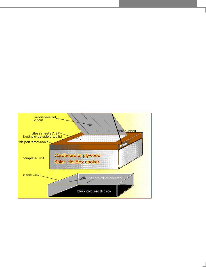
Construction of solar box cooker
Advice on how to build one
Materials needed
5 large pieces of cardboard (see#2 TIPS AND STRATEGIES);at least two should be 4 and one half feet across;Flatten cartons from bicycles,appliances or furniture are excellent (see step 1A,alternated reflector regarding cardboard)
50 feet regular aluminium foil 12 inches wide.
PAGE 16 OF 91

FREE ENERGY PROJECTS 2
1pint white glue.
window glass 20'' by 24"
* 8 feet wood molding:window screen moulding is best(see section on alternate Reflector)
one tube clear silicone caulk
4 feet slash cord or similar heavy string
Insulation 2 inch stack of newspapers
Black metal tray approx 17 inches by 21 inches (see step 4 cooker completion)
Masking tape.
Tools needed:
Box cutter or sharp knife
Pan or bowl to mix glue.
brush or small roller to spread glue.
Straight edge (eg yardstick) plus blunt tools pliers handle or large screwdriver ) for scoring cardboard.
Saw
3/16" drill
Caulk gun
Tools for holding cardboard while glue dries( eg clamps,clothes pin bricks masking tape etc.)
Scissors
Tips and Strategies
1 Cut all patterns with scissors on solid lines;dotted lines show where cardboard will be folded. Place patterns and hold in place using masking tape.
2 regular cardboard is easier to work with than double strength cardboard and is satisfactory for most parts of the box.Double strength cardboard is useful for the reflector and lid and may avoid need for reinforcement.
3 Use full strength glue for fastening cardboard pieces together;dilute half glue;and water) for glueing foil to cardboard.
4 Score cardboard (using straight edge and blunt instrument )prior to folding .Score on the side toward which the fold is to be made in order to avoid tearing the cardboard.All folds are UP,towards the side on which pattern was placed .Except narrows flaps on the inner box ,which are scored on the reverse side and folded in opposite direction.
5 Place pattern on cardboard to take advantage of folds pre-existing on cardboard,otherwise place patterns on cardboard so that the new folds are as far way from pre-existing folds as possible.
PAGE 17 OF 91

FREE ENERGY PROJECTS 2
6 When working on the floor don't kneel on the cardboard you are going to use;it makes dents.kneel on a scrap of cardboard it protects the knees.
7 Start with the lid;there are several step; requiring glue to dry in between, go to another part of the box while it is drying.
8 A second piece of glass is useful in marginal weather (where there is wind or intermittent clouds,place on top of lid to avoid heat loss.
Step 1 Construction of the lid
After cutting and scoring cardboard fold tabs at corners outside the side flaps and glue,securing with clamps and or tape.
Allow time for glue to dry before proceeding.
Invert top and adhere glass to underside of top using silicone caulk.Make a bead of caulk about 1/2 inch in from the edge.Press flat with something heavy until dry.Fill in the space between the glass and sides of top with strips of cardboard about 2 inches wide (measure to fit exactly) and glue in place.
After caulk is dry on underside ,invert top and put a bead of caulk around glass window where it is framed by the cardboard.
Step 1A Construction of the Reflector.
Pattern is design to provide a reflector from the same piece of cardboard from which the lid is made.
Simply cut along the three dotted lines in the center of the pattern and score on the reverse s(top of lid) of the fourth side providing a large flap which will serve as the reflector.
An ALTERNATE REFLECTOR (which provides a larger reflecting surface and protects the window better when cooker is not in use) can be made by cutting a separate piece of cardboard (double strength cardboard is useful here) to fit the full size of the lid.In this case the larger flap provided by following the pattern will be cut off along the fourth side and removed. This is a piece can be later used to improvise a drip pan (see section on cooker completion).
Which ever reflector is used .completely foil the side facing towards the glass. If the alternate reflector ,score three inches from the edge of the back side and glue to lid.
If regular strength cardboard has been used ,it is suggested that the reinforcement sticks be glued to the three unsupported edges of the reflector.
Prop mechanisms for the reflector.
[A] Punch holes through side of the lid and reflector.Tie stick in each location so that in each location so that it can be slid up and down to adjust the reflector.
or
PAGE 18 OF 91

FREE ENERGY PROJECTS 2
[B] Glue blocks of wood about 3/8" thick 6 inches to 8 inches long,with holes drilled in side to lid and reflector .Use heavy wire( such as from coat hanger) for support
Construct an inner box to fit inside larger box on all side of this inner box glue the al foil to each inner side.
ADD black metal pan to bottom of inner .It is essential to have a black drip pan in the bottom of the cooking chamber.
If a metal pan is not available it is satisfactory to improvise a pan by covering one side do a piece of cardboard with foil cutout and then painting the foil black
GETTING BOX READY TO COOK
After the box is complete ,but before cooking allow box to dry several hours in hot sun so that no chemical odours from glue or caulk are absorbed by food.
Make sure there is a black drip pan in the bottom of the box and that any cooking pots have black or dark lids.
Finishing touches.
Line the underside of the lid with foil in order to cover all spaces between glass and cardboard.
Cover all corners with two inch paper tape such as sheet rock tape or brown paper bags cut into two inch strips using full strength glue.
This helps protect the corners.Don't use pre adhesive tape, such as masking tape or duct tape ,as it fails to hold up against repeated exposure to sunlight.
Make short feet for your cooker of 2 inch squares of wood ,plywood or several layers of cardboard to protect the bottom of cooker.
Cover cooker with wallpaper ,cloth,contact paper or exterior paint. two coats of exterior paint are especially helpful in making your cooker more waterproof.
The information provided came from an individual know to me as IM
A solar water heating system based on the hot has been also constructed to provide hot water. A simple diagram is presented below.
PAGE 19 OF 91
FREE ENERGY PROJECTS 2
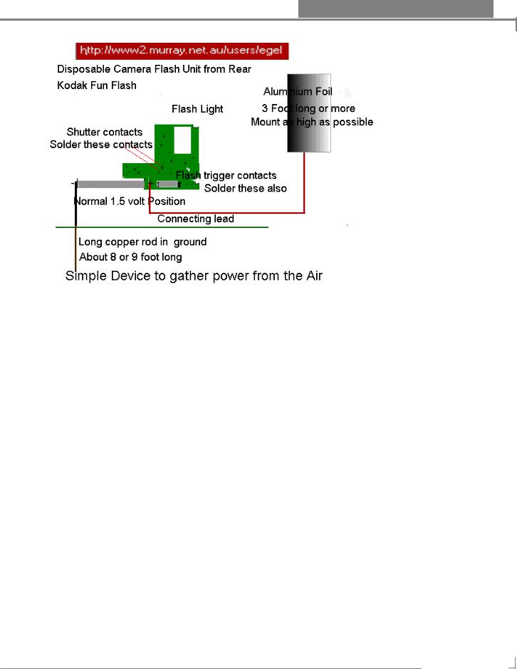
The Free energy Flasher
I haven't yet finished building this device but my contact in Houston
Texas assures me it will work
The details sent me are thus:
Try this...get one of those cheap one shot use disposable cameras, tear it apart, carefully...find the wires that go to the shutter switch and short then out, connect them together so that they are constantly 'on'
(** the one I tried a Kodak Fun Flash came apart quite easily it does not need a lot of force ** )
Then take out the batteries.... |
put a long rod into the ground... |
8 or 9 feet |
long...then connect that copper |
rod to the (-) negative side of |
where the |
batteries hooked up to the camera's strobe... |
|
|
Make a piece of metal, alumimun foil, large and as long as you can, 3 feet long at least, attach it to a wooden pole, just don't let it get grounded okay...then attach (+) lead that went to the batteries to it.
(note ** A high single length of wire aerial may also serve the same purpose as the al foil , it may be also wise to use something other than wood as your support as this will become conductive to the ground when the wood becomes wet,use maybe plastic or rubber spacers to attach the foil to mast ** )
PAGE 20 OF 91