

Phedotikov / 1 / FreeEnergy_27.01.08 / !Информация / Free Energy Projects
.pdfFREE ENERGY PROJECTS 2
the magnetic field would have a greater influence on the planet pulling it towards this magnetic field. Whilst at other times the sun would have a greater influence and tend to repel the planet away ,the combination of these two forces would balance out to give an appearance of an elliptical planetary orbit. Pure conjecture or is it? You decide for yourself.
Battery free energy claim
There are a number variations on this theme. Some are all electronic and have electronic all switching [power transistors] driven by a variable electronic sine wave generator. In reality they are the following design as illustrated. A twelve volt lead acid battery will usually deliver a voltage of between 12 and 13.5 volts, therefore to charge this battery a voltage greater than this would be needed. To achieve this four batteries are used, in one half of the switching cycle two batteries are connected in series to give 24 volts and fed to the other two connected in parallel as 12 volts. In the other half cycle the batteries previously charged as twelve volts are now a parallel connection of twenty four volts and are now charging the other two as twelve volts. On the diagram the green circles represent switches that are activated by motorised activator and are in either on or off mode together. The blue circles represent the other set of switches and are off when the green ones are on. The arrows represent
PAGE 61 OF 91

FREE ENERGY PROJECTS 2
power diodes and that help direct the power flow. The key to making this device work seems to be the frequency of the switching operation. This is achieved by a variable speed electrical motor driving a set of insulated disks with metal contacts fixed to wheels The wheels themselves making intermittent contact with outer part of the switch [see diagram] when rotated. A power rectifier and a full wave bridge convert the pulsating current to a dc supply. Apparently the right resonance switching triggers something in the chemical and electrical characteristics to give better charging than expected and resulting in claims of over unity power from some constructers.
Hendershot Electrical Generator
The Hendershot Electrical Generator. During the 1920's an Inventor in the United States called Lester Hendershot produced a device which claimed produced useful power of a about 300 watts. The device proved however to be erratic in operation. The inventor claimed he was tapping the space energy field. The Hendershot generator consists of a special arrangement of two basket weave coils with each of them being of three coils themselves. Each basket weave coils were placed around a stainless steel cylinder upon which before a full capacitor al foils had been wrapped. The unit also consisted of two transformers of 5:1 transformers, magnetic clapper unit, from which the unit was triggered and additional capacitors. For those who are interested in the full
PAGE 62 OF 91
FREE ENERGY PROJECTS 2
construction details, his son Mark Hendershot who is trying to continue the work, has available a full set of construction plans of the generator and details of his father's life work. A copy can also be obtained from the Tesla bookshop
.
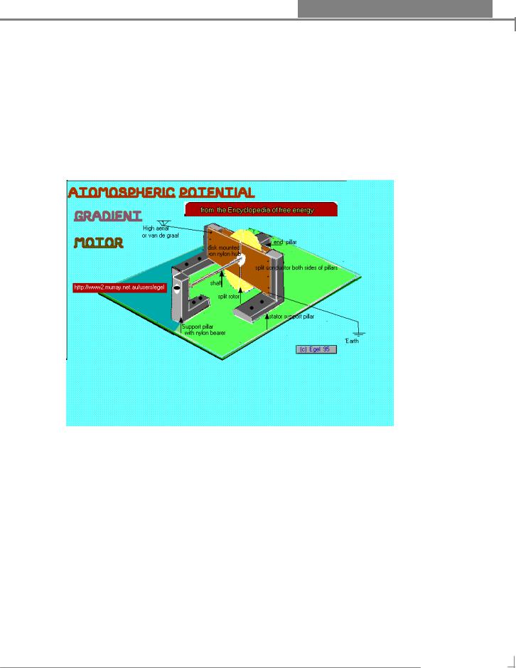
Atomospheric Motor
Atmospheric Potential Gradient Motor A simple motor using electrostatic energy gathered from the air or from a electrostatic machine. The device consists of one split armature of two semi circular metal disks mounted on a smaller insulated disk mounted to a common axle. On the arm supports are bolted four metal face plates one to left ,one to right in the front and two in the rear of the rotor. The face plates cover the entire disk surface with a gap through the centre where they are not joined and where the axle comes through. The Face plates on the left hand are connected to an aerial as long as possible to gather sufficient static electricity. A small piece of wire is soldered to the face plate and the other end makes contact with the rotor plate. The right hand side is similar except it is connected to good earth. How it works The unit works by the aerial gathering a static charge from the air and transferring it to the left face plates and then to the rotor face. As both metals now have the same charge a repelling effect takes place and the other side of the rotor with
PAGE 63 OF 91

FREE ENERGY PROJECTS 2
an opposite charge is attracted to this position. As soon as the rotor face come into contact with the solder wire it acquires the same charge and the process is repeated. A high aerial or good electrostatic machine is a must along with a good earth. The unit is built from Plastic and aluminium. The axle supports should not be tight as to prevent the rotation of the axle. The measurement and construction details are under construction.
PAGE 64 OF 91

FREE ENERGY PROJECTS 2
Water and glass Capacitor
If you have ever over charged an electrolytic capacitor and then shorted the leads out you can see the wallop this little package can deliver in a short space of time. Some of the big ones left to themselves can build up a charge big enough to kill people. These usually carry a warning to discharge them properly before use. A question though if there is no free energy where did this power come from? The main purpose of a capacitor is to store electrical energy and their beginnings can be traced back to the Leyden jar when the only electricity was static energy produced by rubbing amber with wool The leyden jar was a glass jar with tin foil coating layers on both sides of jar Nicola Tesla described capacitors as the electrical equivalent of dynamite. The capacitor can be made of many materials some of which are listed below. it usually consist of two conducting plates sandwiched around an insulator. The thickness and type of insulator and the size of the plates determines the electrical charge it can hold. Some typical materials used in construction Electrolytics and bipolar electrolytics use a chemical substance to help store the energy Resin dipped electrolytics which use a tanatalum dielectric Polystyrene , Plastic Film Capacitors , Ceramics oil, oil paper, aluminium, glass I have seen one constructed using a book with tin foil plates alternately connected to each other on each page , for a tuning capacitor in a crystal set. The tuning was affected by putting pressure on the book covers and squeezing tight. Most of the above are hard for the experimenter to construct,
PAGE 65 OF 91

FREE ENERGY PROJECTS 2
however there is one almost anyone can make and comes in two variants. Acquire two jars nearly the same height but different in diameter Place one jar inside the another. Have a brass rod to both sections and then fill both jars with water. Leave the water levels down on jars so that water cannot flow into one another. If you want to improve the appearance, you could make a top of cork or,plastic to hold both jars together and bolt the brass rod through the top, both brass rods need to insulated from one another. Use both rods as capacitor connections. The other variant is even easier Get a collection of jars or bottles fill each with water each jar must have a common electrical connection to each others water. Place all of them on a on metal tray and fill tray with water Place a connection on tray ,both wires now form the leads to your condensor. Experiment with water by adding salt to water to improve conductivity. I think that we, are yet to know everything about water and we may be surprised what else we can do with it.
Making a normal capacitor If you wish to make a normal capacitor here are some ideas how to achieve it. You will need some aluminium foil the type sold on cardboard rolls The more foil used the better the charge it will store. You will also need some wax proof paper You will also need any type of polymer resin as long as it is sticky. any paint shop should be able to sell you some. First place a length of the wax paper down and coat with the resin Next comes a layer of tin foil. Then another layer of resin coated wax paper Then the final layer of aluminium foil. By the way it may be wise to have the wax paper wider than the tin foil. Roll all the layers together tightly to form a cylinder, and using former core may be a good idea to wrap layers upon. May sure there is way you can make electrical wiring connections to both foil layers and apart from this no other electrical contact is to be made between foil layers. There you have it. The biblical capacitor In the Christian Holy bible there is a description of the ark of the covenant that Moses and the Jewish people built that some say was nothing more than one really powerful self charging capacitor. Certain instructions with the metals and silk screens seem to confirm it. There were also instructions to those that were to carry and manage and look after to the ark which seem like to me a Faraday Cage Protection scheme. There is also a report in the bible that one unprotected individual touched the ark and was killed while trying to stop it from falling. If you wish to check this you can find it in the Old Testament book of Exodus chapter 25 verse 1 to chapter 29 I heard a report that a American citizen had also built one but found it to dangerous to have around and thus dismantled it.
PAGE 66 OF 91

FREE ENERGY PROJECTS 2
Liquid Piston Pump
Electo magnet pump
This is a device which makes the use of Fleming's right hand rule which if drawn would represent in all directions in a three dimension space that is [up,down] [left,right] [front,back] Take one line to represent the direction of the magnetic field another to represent the flow of the current and the final one to represent the direction of motion. This holds true from all combinations of magnets, current and direction in any form of motor. A motor usually consists of a stationary magnetic field called the stator and in the middle a rotating magnetic field called the armature fed by a direct current alternated by commuter. In this design there is no moving core except the motion of the liquid salty water. Construction Please remember this only an Experimental Idea Obtain a P.V.C. pipe and cut to length desired. drill two holes directly opposite one another each side of the pvc and insert brass nuts and bolts These will be the means by which electrical current will flow from one contact through the water and to the other contact. Seal around bolt holes so that they cannot leak water. Take two leads from these points. Now mount two magnets permanent or electro magnets over top of the contacts and fix into position. If you wish to use permanent magnets go to a local vehicle wrecker and obtain a windscreen wiper motor . Disassemble the motor usually with a hack saw and remove the armature section. You should know have easy access to the
PAGE 67 OF 91

FREE ENERGY PROJECTS 2
curved magnets inside. These will fit ideally around the pvc tubing of the correct size and could be held in place with electrical insulation tape. Set up tube and fill with salty water connect up the field coils if not a permanent magnet and pass a current through the contacts. With the correct voltage, current and water conductivity. This you will need to determine by experimentation. Water should then flow in one direction or the other. With greater magnetic strength and wider current flow across the direction of water flow ,this could conceivable be used as a device to propel an aquatic vehicle across water. Nuclear power stations already imploy something similar in the reactors.
Related Article
I came across this idea in some papers I received The idea seems to originated from some one called Richard Lefors Clark Ph.D dated 18/3/86 4015 Crown Point drive P-3 San Diego CA 92109 He seems to suggest a way to generate a strong diamagnetic field by pumping water through copper tubing wound in a spiral helix using a normal water pump. He also seems to suggest that by putting four to six coils on a platform and then turned upside he could levitate the platform. Professor Clark suggests that if put a normal electric current through the tube we get a strong normal magnetic field. Suggests also that the connection of diamagnetism and electrical effects has hidden the true nature and utility of diamagnetism. For evidence he quotes an experiment performed by Oersted
PAGE 68 OF 91

FREE ENERGY PROJECTS 2
Now with water flow in the copper coil only Connect a loop of wire in a complete circuit with an ammeter. Move the copper wire coil close to the water carrying helix copper at close range. No magnetism but electrical current is produced in the ammeter circuit. He also seems to suggest that we need high speed flow pumps and directional flow coils to improve the design. Maybe the two designs in this article could be linked to create the above flow pumps. Wind coil mentioned in this second article like normal dc coils are wound. Start at one end and tightly wind down in spiral path until one layer is finished and in one rotation back to the top then back down again as at the start. Editor's note If what the professor suggests is correct, think of what kind of new motors and generators could be made, perhaps better performing than those we have now.
Sonic Levitation
Question
Put an egg in a glass and watch it sink. How can you get it to come to the top without touching it? Answer Easy if you know how By adding salt to the water and waiting for it to dissolve will make the egg rise. The surrounding area around the egg has changed and the gravity effect has been altered. Maybe
PAGE 69 OF 91

FREE ENERGY PROJECTS 2
by the addition of sound waves to an area sounding an object and to the object the effects of gravity can be changed also time will tell.
THE PAST Lifting heavy weights has always been difficult. But if the following story is true, there may have been in the distant past an easier way This is story that has been passed to me and I have two versions two different Locations but the details seem to be similar. It seems an Oxford MD had a Tibetan student friend who invited him to Tibet and whilst there he witnessed the following He was taken to a monastery where a building operation was underway. At the scene he noticed that at 250 metres above ground level there was a cliff with a cave. He saw monks were busily building a wall on a small area in front of the said cave. At ground Level there laid a smooth flat stone with a large indentation in it one meter across by 15 centimeters deep. A block of stone about 1 by 1.5 meters was placed into this area At a distance of 63 metres from the container 19 musical instruments including (ragdonds) were placed together in a 90 degree arc. * I believe ragdongs are long wind blown pipes that produce a low frequency tone *. All Distances had been carefully measured. The instruments consisted of 13 drums and 6 trumpets, Eight of the drums were 1 meter wide and 1.5 meters long. Four were medium sized 0.7 by 1 metre There was also a small one 0.2 by 0.3m The drums were made from 3mm thick sheet metal and weight 150kg with one end open. The operators stood behind their instruments when playing them. The small drum was used to signal a control to start. This resulted in the monks singing a mantra and the instruments making a loud low droning noise and drum noise. It seems for about four minutes nothing happened. When the tempo was increased the stone began to sway and then levitated towards the cave opening Three minutes later it landed on the platform at the cave opening. In one hour so the story goes they lifted 5 to 6 stones into position. For this story to be true the stones would have needed to have flown in a 500m long parabolic curve and a height of 250 metres. The drums and trumpets were placed in an equal order and each trumpet was separated by drums.
PAGE 70 OF 91