

Measurement and Control Basics 3rd Edition (complete book)
.pdfChapter 5 – Pressure Measurement |
145 |
5.3A sample of gas occupies a fixed volume at a pressure of 15 psia and a temperature of 30°C. Find the pressure of the gas if the temperature of the gas is increased to 40°C.
5.4Find the gauge pressure if the absolute pressure reading is 50 psia and the local barometric pressure is 14.5 psi.
5.5Find the absolute pressure if the reading of a pressure gauge is 21 psig and the local barometric pressure is 14.3 psi.
5.6Find the displacement in inches for a mercury manometer with a specific gravity of 13.54, if the pressure applied is 1 psi.
5.7Calculate the pressure detected by a U-tube manometer if the liquid in the manometer has a specific gravity of 2.95 and it is displaced 20 inches when pressure is applied.
5.8Calculate the pressure detected by a mercury manometer if the mercury is displaced 4 inches. The specific gravity of the mercury in the manometer is 13.54.
5.9List the sensing elements commonly used in pressure gauges.
5.10List the two methods used in capacitance-type pressure sensors to detect the capacitance change produced by a pressure change.
5.11A pressure instrument has a span of 0-100 inH2O. A measurement
results in a value of 50 inH2O for pressure. Calculate the error if the accuracy is (a) ±2.0% FS, (b) ±1.0% of span, and (c) ±0.5% of reading. What is the possible pressure in each case?
5.12Find the change in wire resistance for a strain gauge that has a
nominal wire resistance of 150 Ω when it is subjected to a strain of
800 µm/m.
5.13Calculate the span of a differential pressure transmitter that is mounted 10 inches below the bottom instrument tap on an open process tank that contains a liquid with a specific gravity of 1.1. Assume that the minimum level in the process tank is 0 inches, and the maximum level is 50 inches.
BIBLIOGRAPHY
1.Johnson, C. D. Process Control Instrumentation Technology, 2d ed., New York: John Wiley & Sons, 1982.
2.Kirk, F. W., and N. R. Rimboi. Instrumentation, 3d ed., Homewood, IL: American Technical Publishers, 1975.
3.Liptak, B. G., and V. Kriszta (ed.). Process Control – Instrument Engineers' Handbook, rev. ed., Radnor, PA: Chilton Book, 1982.
146Measurement and Control Basics
4.Murrill, P. W. Fundamentals of Process Control Theory, 3rd ed., Research Triangle Park, NC: ISA, 2000.
5.Ogata, K. Modern Control Engineering, Englewood Cliffs, NJ: Prentice-Hall, 1972.
6.Weyrick, R. C. Fundamentals of Automatic Control, New York: McGraw-Hill, 1975.

6
Level Measurement and Control
Introduction
This chapter discusses the basic principles of level measurement and control in industrial process applications. Sensing and controlling product levels in containers involve a wide range of materials, including liquids, powders, slurries, and granular bulk. In all level measurement a sensing device, element, or system interacts with material inside a container. A wide variety of physical principles are used to measure level. Common types include sight, pressure, electric, sonic, and radiation—each of which we discuss here. We will also explore level switches and a level control application.
Sight-type Instruments
There are three common sight-type level sensors: glass gauges, displacers, and tape floats. Glass gauges are the most widely used instruments for measuring the level in a process tank.
Glass Gauges
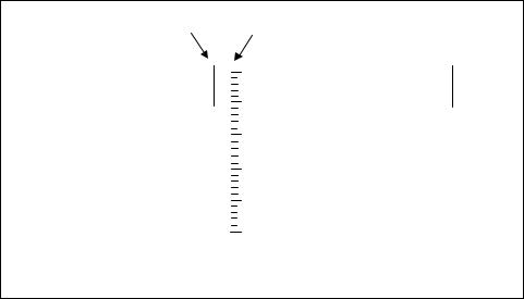
Two types of level glass gauges are used to measure liquid level: tubular and flat. The tubular type works in the same way as a manometer, that is, as the liquid level in a vessel rises or falls the liquid in the glass tube will also rise or fall. The gauges are made of glass, plastic, or a combination of the two materials. The material from which the transparent tubes are made must be able to withstand the pressure in the vessel, and they are generally limited to 450 psig at 400°F. Figure 6-1 shows two common applications of tubular sight glasses: an open or vented process vessel and
147
148 Measurement and Control Basics
|
open-end |
|
|
|
Calibrated |
|
|
|
||||||
|
|
|
|
Scale |
|
|
|
|||||||
|
|
|
|
|
|
|
|
|
|
|
||||
|
|
|
|
|
|
|
|
|
|
|
|
|
|
|
|
|
|
|
|
|
|
|
|
|
|
|
|
|
|
|
|
|
|
|
|
|
|
|
|
|
|
|
|
|
|
|
|
|
|
|
|
|
|
|
|
|
|
|
|
|
|
|
|
|
|
|
|
|
|
|
|
|
|
|
|
|
|
|
|
|
|
|
|
|
|
|
|
|
|
|
|
|
|
|
|
|
|
|
|
|
|
|
|
|
|
|
|
|
|
|
|
|
|
|
|
|
|
|
|
a) Open or Vented Vessel |
b) Pressurized Vessel |
Figure 6-1. Tubular sight glass gauges
a pressurized vessel. For the pressurized tank, the upper end of the tube is connected to the tank. This creates an equilibrium pressure in both ends of the tube, and the liquid in the tube rises to the same level as the liquid in the vessel. A calibrated scale is normally mounted next to the sight gauge to indicate the level in the tank.
The pressure that the liquid exerts in the tank forces the liquid in the sight glass to rise to the same level as the liquid in the tank, as shown in Figure 6-1. You can calculate the pressure in the tank in psig using the Equation P= (0.03606)(SG)h, if the height of the liquid is given in inches. Example 6-1 illustrates this calculation.
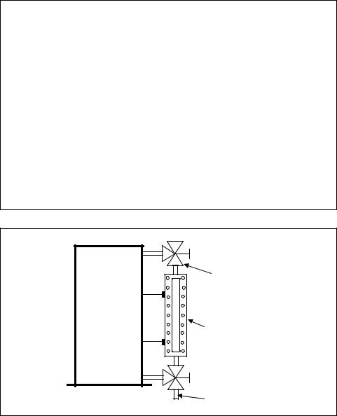
The bodies of flat sight gauges are either made of metal castings or forgings and a heavy glass or plastic front for viewing the level. A typical flat gauge design is shown in Figure 6-2.
There are two basic types of flat sight gauges: reflex and transparent. The reflex-type gauge produces a dark area where liquid is present and a light area where vapor is present. The reflex type gauge is normally chosen for liquids that are colorless, clear, and nonviscous. The transparent gauge is generally used when the liquid is colored, viscous, and corrosive.
Sight glass gauges are installed with manual shutoff valves at both ends. This isolates the gauges so maintenance can be performed, as shown in Figure 6-2. It is common practice to use ball-check valves for the shutoff valves because they will stop flow if the gauge glass breaks.
Chapter 6 – Level Measurement and Control |
149 |
EXAMPLE 6-1
Problem: Calculate the pressure in psig that is detected by a tubular sight glass gauge if the height of the liquid is 50 inches and the specific gravity of the liquid in the tank is 1.2.
Solution:
P = (0.03606)(SG)h
P = (0.03606)(1.2)(50 inches)
P = 2.16 psig
The flat glass gauges are the most common type of sight gauges used in the process industries. They are used in a very wide range of pressure and temperature liquid services and in applications in which pressure and temperature are as high as 10,000 psig and 1000°F.
Manual Valve
Flat Glass Gage
Drain
Figure 6-2. Flat sight glass gauge
Displacers
Displacer level gauges operate on Archimedes’ principle: they use the change in buoyant force acting on a partially submerged displacer. Archimedes' principle states that a body fully or partially immersed in a fluid is buoyed up by a force equal to the weight of the fluid displaced.

150 Measurement and Control Basics
In equation form, Archimedes’ principle for the buoyancy force, B, is given by the following:
B = Wd = ρ gV |
(6-1) |
where
Wd |
= the weight of the displaced fluid |
ρ= the density of the displaced fluid
V |
= |
the volume of the displaced fluid |
g |
= |
the gravitational constant. |
The quantity ρ g is often called the weight density of the fluid; it is the weight per unit volume of the fluid. For example, the weight density of water is 62.3 lb/ft3 at 20°C. Thus, the following equation gives the buoyancy force for a volume (V ) of water at 20°C that is displaced by a body:
B = (62.3lb/ft3)V |
(6-2) |
Example 6-2 illustrates how to calculate the buoyancy force on an object that displaces water.
EXAMPLE 6-2
Problem: Calculate the buoyancy force on an object that displaces 2.0 ft3 of water at 20°C.
Solution: Using Equation 6-2 to determine the buoyancy force, we obtain the following:
B = (62.3 lb/ft3) V
B = (62.3 lb/ft3) (2.0 ft3)
B = 124.6 lb
By measuring the buoyancy force produced by a displacer, you can determine a level value. If the cross-sectional area of the displacer and the density of the liquid are constant, then a unit change in level will result in a reproducible unit change in displacer weight.
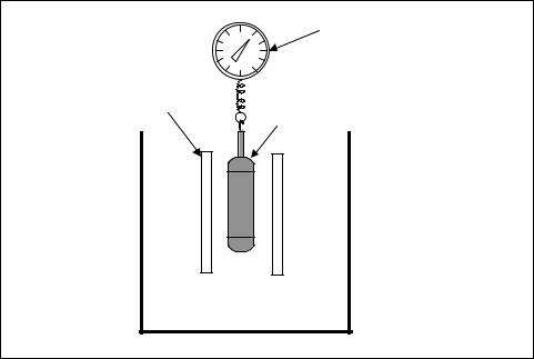
The simplest level device of the displacer type consists of a displacer in a stilling well, which is suspended from a spring-weight scale, as shown in Figure 6-3.
Chapter 6 – Level Measurement and Control |
151 |
Weight Scale
Calibrated for Level
Stilling Well
Displacer
Figure 6-3. Displacer level gauge
The level scale can be calibrated from 0 to 100 percent, or in other level units.
Tape Float
Figure 6-4 shows one of the simplest, most direct methods for measuring level: the tape float. In the unit shown, a tape is connected to a float on one end and to a counterweight on the other to keep the tape under constant tension. The float motion makes the counterweight ride up and down a direct-reading gauge board. The gauge board is calibrated to indicate the liquid level in the tank.
Standard floats are normally cylindrical in shape for top-mounted designs and spherical or oblong for side-mounted designs. Small-diameter floats are used in higher-density materials; larger floats are used to detect liquidliquid interface or for lower-density materials.
Pressure-type Instruments
Numerous sensors use basic pressure principles to measure level. The three common types that we will discuss here are differential pressure, bubblers, and diaphragm.

152 Measurement and Control Basics
100
Float |
75 |

 50
50
25
0
Weight
Figure 6-4. Tape float gauge
Level Measurement by Differential Pressure
Figure 6-5 shows a common open-tank differential pressure transmitter. In Chapter 5, we saw that there is a direct relationship between the hydrostatic pressure caused by a column of liquid, the specific gravity of the liquid, and the height of the vertical column of liquid. In most cases, the specific gravity of a fluid is constant, so pressure (P) is directly proportional to liquid level (h). This gives us
P = Kh |
(6-3) |
where K is a proportionality constant.
Atm.
dP Transmitter
Pneumatic Signal
 proportional to
liquid level


 Atm.
Atm.
Hi |
Lo |
Figure 6-5. Level measurement (open tank)

Chapter 6 – Level Measurement and Control |
153 |
In the open tank shown in Figure 6-5, the differential pressure (dP) transmitter converts the pressure of the liquid level into a pneumatic signal. Normally, a 3-to-15-psi pneumatic signal or 4-to-20-maDC current signal is used to represent the liquid level in the tank. The high side of the dP cell is connected to the bottom of the tank, and the low side of the dP cell is open to the atmosphere. Since the tank is open to the atmosphere, the pressure of the liquid on the high side of the dP transmitter is directly related to the level in the tank.
Figure 6-6 shows another application that uses a dP transmitter: measuring the level of a closed tank. In the example in Figure 6-6, if the pressure in the closed tank changes, an equal force is applied to both sides of the dP transmitter. Since the dP cell responds only to changes in differential pressure, a change in the static pressure on the liquid surface will not change the output of the transmitter. Thus, the dP cell responds only to changes in liquid level. In this example, a 4-to-20-maDC current signal is used to represent the level in the tank.
Electronic signal 


 proportional to
liquid level
|
|
|
Lo |
Hi |
|||
|
|
|
dP Transmitter |
Figure 6-6. Closed tank level – differential pressure
Bubblers
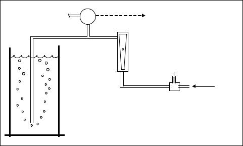
Another example of a pressure-type level instrument is the bubbler system shown in Figure 6-7. When you use bubbler systems to measure liquid level, you install a dip tube in a tank with its open end a few inches from the bottom. A fluid is forced through the tube; when the fluid bubbles escape from the open end, the pressure in the tube equals the hydrostatic head of the liquid. As liquid level varies, the pressure in the dip tube changes correspondingly. This pressure is detected by a pressure-sensitive
154 Measurement and Control Basics
Atm. |
LT |
Level signal |
|
Visual |
|
|
Flow |
|
|
Indicator |
|
|
|
Plant air |
|
|
Pressure |
|
|
Regulator |
Figure 6-7. Air bubbler system
instrument if you need continuous indication of level or by pressure switches if you need on/off level control of the tank level.
The purge supply pressure should be at least 10 psi higher than the highest hydrostatic pressure the process will encounter. You should keep the purge rate small, about 1 scfh, so no significant pressure drop occurs in the dip tube. Usually, the purge medium is air or nitrogen, although you can use liquids as well.
If you have a tank that operates under pressure or vacuum, installing a bubbler system becomes slightly more complex. This is because the measurement of liquid level is a function of the difference between the purge gas pressure and the vapor pressure above the liquid. Because differential pressure is now involved, the transducer that is used is normally a dP cell.
There are some disadvantages to using bubblers. The first is limited accuracy; another is that bubblers will introduce foreign matter into the process. Also, liquid purges can upset the material balance of the process, and gas purges can overload the vent system on vacuum processes. If the purge medium fails, not only do you lose the level indication on the tank, but the system is also exposed to process material that can cause plugging, corrosion, freezing, or safety hazards.
Diaphragm
Diaphragm detectors operate by the simple principle of detecting the pressure that the process material exerts against the diaphragm. Figure 6-8