

2.5 COMMUNICATION,
NAVIGATION & SURVEILLANCE
COMMUNICATION FREQUENCY WINDOW
The Communication (COM) Frequency Window, located in the upper right corner of the PFD, provides control and display of dual VHF Radio Communication Transceivers (COM1 and COM2). The COM Frequency Window displays the following information:
•COM1 and COM2 active and standby frequencies
•Color-codedindicationoftheactiveCOMtransceiver
NOTE: Operating procedures for the COM Frequency Window are located in the VHF NAV/ COM section.
PRIMARY FLIGHT DISPLAY
|
Active COM |
|
Standby COM |
|||||||||
|
Frequency Field |
|
Frequency Field |
|||||||||
Selected COM |
|
|
|
|
|
|
|
|
|
|
|
|
|
|
|
|
|
|
|
|
|
|
|
|
|
|
|
|
|
|
|
|
|
|
|
|
||
|
|
|
|
|
|
|
|
|
||||
Radio |
|
|
|
|
|
|
|
COM Radios |
||||
|
|
|
|
|
|
|
||||||
(Green) |
|
|
|
|
|
|
|
|
||||
|
|
|
|
|
|
|
|
|||||
|
|
|
|
|
|
|
|
|
|
|
|
|
|
|
|
|
|
|
|
|
|
||||
|
|
Frequency |
|
|
|
Frequency |
||||||
|
Toggle Arrow |
|
|
|
Tuning Box |
|||||||
Figure 2-33 Communication Frequency Window
NAVIGATION FREQUENCY WINDOW
The Navigation (NAV) Frequency Window, located in the upper left corner of the PFD, provides control and display of dual VOR/ILS receivers (NAV1 and NAV2). The NAV Frequency Window displays the following information:
•NAV1 and NAV2 active and standby frequencies
•NAV1 and NAV2 identifier, if the active NAV1 or NAV2 frequency is a valid, identified frequency
•Color-coded indication of the active NAV receiver
NOTE: Operating procedures for the NAV FrequencyWindowarelocatedintheVHFNAV/COM section.
|
|
|
Standby NAV |
|
Active NAV |
||||||||
|
|
|
Frequency Field |
|
Frequency Field |
||||||||
NAV Receivers |
|
|
|
|
|
|
|
|
|
|
|
|
Selected NAV |
|
|
|
|
|
|
|
|
|
|
|
|
||
|
|
|
|
|
|
|
|
|
|
|
|
||
|
|
|
|
|
|
|
|
|
|
Radio |
|||
|
|
|
|
|
|
|
|||||||
|
|
|
|
|
|
|
|
|
|
|
|
|
(Green) |
|
|
|
|
|
|
|
|||||||
|
|
|
|
|
|
|
|
|
|
|
|
|
|
|
|
|
|
|
|
|
|
|
|
|
|
|
|
|
|
|
|
|
|
|
|
||||||
|
|
|
Frequency |
|
Frequency |
||||||||
|
|
|
Tuning Box |
|
Toggle Arrow |
||||||||
Figure 2-34 Navigation Frequency Window
190-00498-00 Rev.A |
Garmin G1000 Pilot’s Guide for Cessna Nav III |
2-21 |
PRIMARY FLIGHT DISPLAY
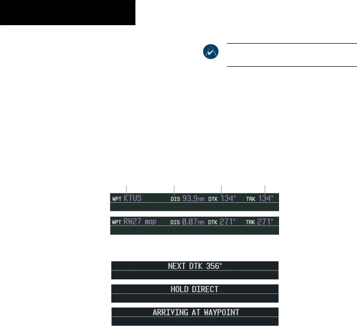
NAVIGATION STATUS BAR
The Navigation Status Bar is located at the top of the PFD and displays valuable information while flying a route:
•The next waypoint in the active flight plan
•Distance to the next waypoint (DIS)
•Desired track to the next waypoint (DTK)
•Current track angle (TRK)
•GPS Navigation Annunciations
NOTE: The fields in the PFD Navigation Status Bar cannot be changed.
|
|
Desired Track |
|
|
Distance to |
To |
|
Next Waypoint |
Next Waypoint |
Next Waypoint |
Current Track |
Figure 2.5.3 Navigation Status Bar Information Examples
Figure 2-35 Navigation Status Bar Messages
2-22 |
Garmin G1000 Pilot’s Guide for Cessna Nav III |
190-00498-00 Rev.A |

TRANSPONDER STATUS BAR
The Transponder Status Bar displays the transponder code, reply symbol, and mode of operation.
Figure 2-36 Transponder Status Bar
TIS (Traffic Information System) surveillance data up-linked by ATC radar through the GTX 33 Mode S Transponder appears on the PFD Inset Map and on the MFD Navigation and Traffic Map Pages (refer to the Multi Function Display section). If the transponder is configured with Automated Airborne Determination, normal operation begins when lift-off is sensed.
When the aircraft is on the ground, the window automatically displays “GND”. The transponder does not respond to ATCRBS (ATC Radar Beacon System) interrogations when GND is annunciated. If a delay time is set in Configuration Mode, the transponder waits a specified length of time after landing before changing to GND mode.
Transponder Operation
Pressing the XPDR softkey displays the second-level softkeys:
•STBY – Selects standby mode (transponder does not reply to any interrogations)
•ON – Selects Mode A (transponder replies to interrogations, as indicated by the Reply Symbol, R; replies do not include altitude information)
PRIMARY FLIGHT DISPLAY
•ALT – Selects Mode C
In ALT mode, the transponder replies to identification and altitude interrogations, as indicated by the Reply Symbol (R). Replies to altitude interrogations include the standard pressure altitude received from an external altitude source (not adjusted for barometric pressure). The ALT mode may be selected in aircraft not equipped with an optional altitude encoder; however, in this case, the reply signal only replies to mode A interrogations. The transponder also responds to interrogations from TCAS-equipped aircraft.
•VFR – Sets the transponder code to the pre-pro- grammed VFR code selected in Configuration Mode (this is set to 1200 at the factory in the U.S.A. only; please refer to ICAO standards for VFR codes in other countries)
•CODE – Displays the transponder code selection softkeys, which include digits 0-7 and BKSP
•IDENT – Activates the Special Position Identification (SPI) Pulse for 18 seconds, identifying the transponder return on the ATC screen
Transponder Code Selection
Transponder code selection is performed with eight softkeys (0-7) providing 4,096 active identification codes. Pushing one of these softkeys begins the code selection sequence. The new code is activated five seconds after the fourth digit is entered. Pressing the BKSP softkey removes one digit at a time until the status bar is empty (refer to the Mode S Transponder section).
190-00498-00 Rev.A |
Garmin G1000 Pilot’s Guide for Cessna Nav III |
2-23 |