

PRIMARY FLIGHT DISPLAY
VERTICAL SPEED INDICATOR
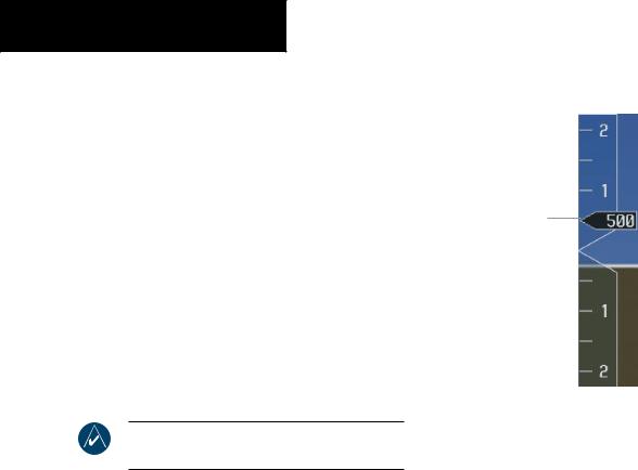
The Vertical Speed Indicator displays the aircraft vertical speed with numeric labels and tick marks at 1,000 and 2,000 feet in each direction on the non-moving tape. Minor tick marks are at intervals of 500 ft.
Vertical Speed Pointer
The Vertical Speed Pointer displays the current vertical speed and points to that speed on the non-moving tape. If the rate of ascent exceeds 2,000 feet per minute, the pointer appears at the top edge of the non-moving tape and the rate in fpm appears inside the pointer. If the rate of descent exceeds 2,000 fpm, a negative sign is displayed in the pointer (-2,000) for negative (down) vertical speed and the pointer appears at the bottom edge of the non-moving tape.
NOTE: Digits appear in the pointer when the climb or descent rate exceeds 100 fpm.
Vertical Speed
Pointer
Figure 2-17 Vertical Speed Indicator
2-14 |
Garmin G1000 Pilot’s Guide for Cessna Nav III |
190-00498-00 Rev.A |
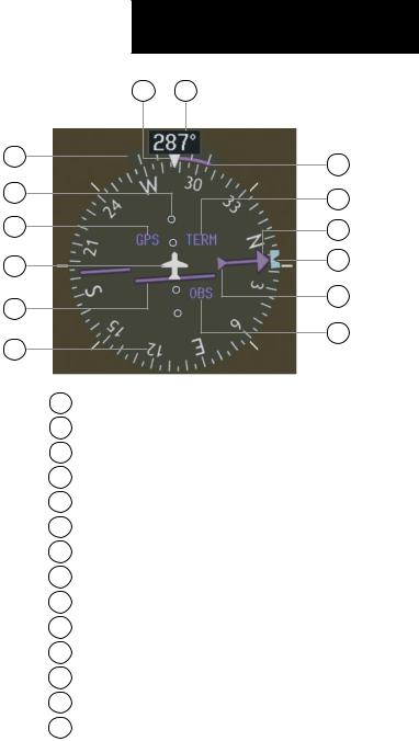
HORIZONTAL SITUATION INDICATOR
The Horizontal Situation Indicator (HSI) displays a rotating compass card with letters at the cardinal points and numeric labels every 30 degrees. Major tick marks are at 10-degree intervals and minor tick marks are at 5- degree intervals. The HSI is displayed in a heading-up orientation. The HSI displays the following information:
•Heading indication
•Turn Rate Indicator
•Course Deviation Indicator
•Bearing pointers
•Bearing Information Windows
•Navigation source
The 360˚ HSI compass rose contains a course deviation indicator (CDI) with a course pointer arrow, a TO/FROM arrow, and a sliding deviation bar and scale. The course pointer is a single-line arrow (GPS, VOR1, and LOC1) or double-line arrow (VOR2 and LOC2) which points in the direction of the set course. The TO/FROM arrow rotates with the course pointer and is displayed when the active NAVAID is received.
|
PRIMARY FLIGHT DISPLAY |
14 |
13 |
1 |
12 |
|
|
2 |
11 |
|
|
3 |
10 |
4 |
9 |
|
|
5 |
8 |
|
|
6 |
7 |
|
1Turn Rate Indicator
2Lateral Deviation Scale
3Navigation Source
4Aircraft Symbol
5Course Deviation Indicator
6Rotating Compass Rose
7OBS Mode
8TO/FROM Indicator
9 Heading Bug
10Course Pointer
11Flight Phase
12Turn Rate and Heading Trend Vector
13Heading
14Lubber Line
Figure 2-18 Horizontal Situation Indicator
190-00498-00 Rev.A |
Garmin G1000 Pilot’s Guide for Cessna Nav III |
2-15 |
PRIMARY FLIGHT DISPLAY
Heading Indication
A digital reading of the current magnetic heading appears on top of the HSI. A rotatable heading bug on the compass rose marks the desired heading.
Figure 2-19 Current Heading
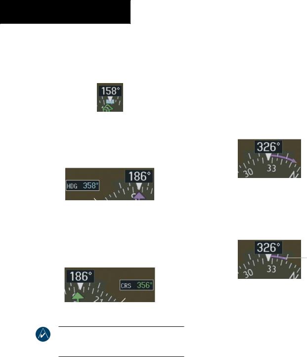
The selected heading appears in a box left of the lubber line, next to the HSI. The color of the digital readout is cyan (light blue).
Turn Rate Indicator
The Turn Rate Indicator is located directly above the rotating compass card. Tick marks to the left and right of the lubber line denote half-standard and standard turn rates. A magenta turn rate trend vector shows the current turn rate. The end of the trend vector gives the heading predicted in six seconds, based on the present turn rate. At rates greater than 4 deg/sec, an arrowhead appears at the end of the magenta trend vector and the prediction is no longer valid.
Half-Standard Turn |
|
|
Turn Rate |
||
Rate Tick Mark |
|
|
|||
Standard Turn |
|
|
|
|
Trend Vector |
|
|
|
|
||
|
|
|
|
(rate > 4 deg/sec) |
|
Rate Tick Mark |
|
|
|||
|
|
|
|||
Figure 2-20 Selected Heading Box
Theselectedcourseappearsinaboxrightofthelubber line, next to the HSI. The color of the digital readout appears in magenta if the navigation source is GPS, or green if the navigation source is NAV1 or NAV2.
Figure 2-21 Selected Course Box
NOTE:TheheadingdisplayedontheHSIisalways magnetic,even if the NAVANGLE is set to‘TRUE’ in the AUX System Setup Page on the MFD.
Figure 2-22 Turn Rate Indicator and Trend Vector
A standard-rate turn (3 deg/sec) is shown on the indicator by the trend vector stopping at the standard turn rate tick mark, corresponding to a predicted heading of 18 degrees from the current heading.
Turn Rate
Trend Vector
(standard rate)
Figure 2-23 Standard-Rate Turn Indication
2-16 |
Garmin G1000 Pilot’s Guide for Cessna Nav III |
190-00498-00 Rev.A |
Course Deviation Indicator
The Course Deviation Indicator (CDI) moves to the left or right of the course pointer along a deviation scale to display aircraft position relative to the course.
The CDI has the same angular limits as a mechanical CDI when coupled to a VOR or LOC. When coupled to GPS, the full-scale limits for the CDI are defined by a GPS-derived distance (5.0, 1.0, or 0.3 nm). The CDI scale automatically adjusts to the desired limits based on the current phase of flight (en route: 5.0 nm, terminal area: 1.0 nm, or approach: 0.3 nm). The desired GPS scale settings may be selected manually on the MFD (refer to the Multi Function Display section).
PRIMARY FLIGHT DISPLAY
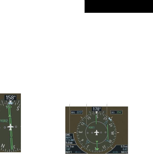
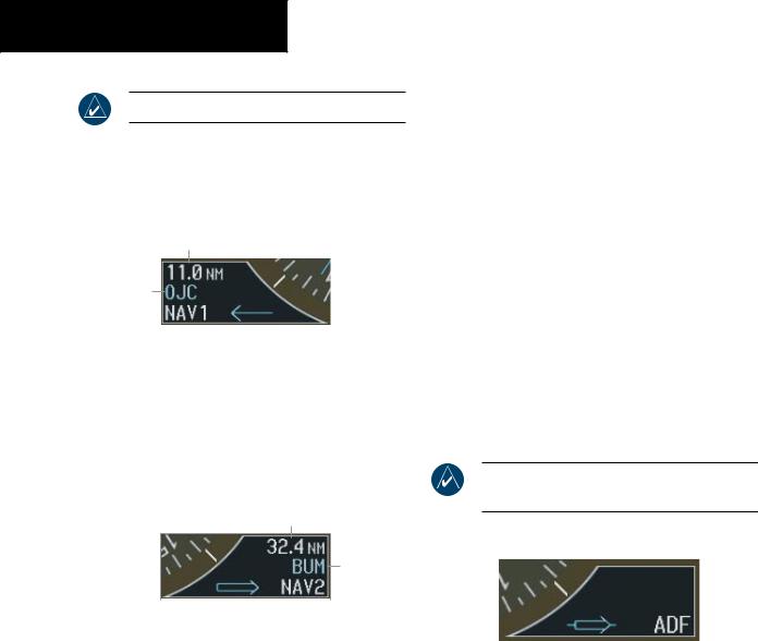
Bearing Pointers and Information Windows
Up to two bearing pointers can be displayed on the HSI. Pressing the PFD softkey provides access to the BRG1 and BRG2 softkeys. The BRG1 pointer is a single cyan line with an open arrowhead at the end. The BRG2 pointer is a double cyan line with an open arrowhead at the end. The bearing pointers never override the CDI. When at least one bearing pointer is displayed (but not necessarily visible if there is no data available), a white ring appears around the center of the compass rose to visually separate the bearing pointer(s) from the CDI.
When a bearing pointer is displayed, its associated information window is also displayed.
DME |
|
Bearing 2 |
Information |
Bearing 1 |
|
Window |
Pointer |
Pointer |
|
|
|
|
|
Figure 2-24 CDI |
Bearing 1 |
Bearing 2 |
||
|
Information |
Information |
||
|
Window |
Window |
||
|
Figure 2-25 |
HSI with Bearing Information |
||
190-00498-00 Rev.A |
Garmin G1000 Pilot’s Guide for Cessna Nav III |
2-17 |
PRIMARY FLIGHT DISPLAY
NOTE: ADF radio installation is optional.
The Bearing 1 Information Window is displayed to the lower left of the HSI and includes the bearing source (NAV1, GPS, or ADF), a pointer icon, frequency (NAV1), and distance (NAV1 and GPS) to the bearing source.
Distance to
Bearing Source
Waypoint
Identifier
|
|
|
|
|
|
|
|
Bearing |
Pointer |
||
Source |
Icon |
||
Figure 2-26 BRG1 Information Window
The Bearing 2 Information Window is displayed to the lower right of the HSI and includes the bearing source (NAV2, GPS, or ADF), a pointer icon, frequency (NAV2), and distance (NAV2 and GPS) to the bearing source.
Distance to
Bearing Source
Waypoint
Identifier
|
|
|
|
|
|
|
|
Pointer |
Bearing |
||
Icon |
Source |
||
Figure 2-27 BRG2 Information Window
If GPS is the bearing source, the active waypoint identifier is displayed in lieu of a frequency. If an active waypoint is not selected, the bearing pointer is removed from the HSI and “NO DATA” is displayed in the information window.
If the NAV radio is the bearing source and is tuned to an ILS frequency, the bearing pointer is removed from the HSI and the frequency is replaced with “ILS”. If the NAV radio is not receiving the tuned VOR station, the bearing pointer is removed from the HSI and the frequency field displays“NODATA”. WhenNAV1orNAV2istheselected bearing source, the frequency is replaced by the station identifier when the station is in range.
ADF Radio (optional)
The ADF radio is a Honeywell KR 87 digital, remotemounted ADF radio receiver that operates in the 200 to 1799 kHz frequency range.
The ADF bearing source is selected by pressing the PFD softkey, then the BRG1 and/or BRG2 softkey until ADF is displayed in the respective Bearing Information Window.
NOTE: ADF frequency is tuned on the KR 87 unit.
Figure 2-28 ADF Selected in BRG2 Information Window
2-18 |
Garmin G1000 Pilot’s Guide for Cessna Nav III |
190-00498-00 Rev.A |
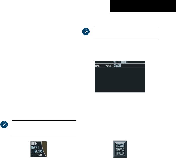
DME Radio (optional)
The optional DME radio is a Honeywell KN63 remotemounted, 200-channel, 100-watt, all-solid-state digital DME which provides distance information to the G1000.
Press the PFD softkey followed by the DME softkey to display the DME Information Window. The DME Information Window is displayed above the BRG1 Information Window. The DME label, tuning mode (NAV1, NAV2, or HOLD), frequency, and distance are displayed in the DME Information Window. When a signal is invalid, the distance is replaced by “–.– – NM”.
The pilot may select from three DME tuning modes:
•NAV1 – Tunes the DME frequency from the selected NAV1 frequency
•NAV2 – Tunes the DME frequency from the selected NAV2 frequency
•HOLD – When transitioning from NAV1 or NAV2 mode to Hold mode, the DME frequency remains set to the last selected NAV frequency.
NOTE: When navigating in GPS mode, the distance displayed is the GPS-derived great-circle distance, not the actual DME distance.
Figure 2-29 DME Information Window
PRIMARY FLIGHT DISPLAY
Radio Tuning Window (optional)
NOTE:The RadioTuningWindow is only available if a DME radio is installed.
The Radio Tuning Window is displayed by pressing the DME softkey. This window provides display and control of the DME radio.
Figure 2-30 Radio Tuning Window
To change the DME mode:
1.From the RadioTuningWindow, turn the large FMS knob to highlight the DME mode field.
2.Turn the small FMS knob to display the selection window. Turn the FMS knob to select the desired mode and press the ENT key.
Figure 2-31 DME Selection Window
190-00498-00 Rev.A |
Garmin G1000 Pilot’s Guide for Cessna Nav III |
2-19 |
PRIMARY FLIGHT DISPLAY
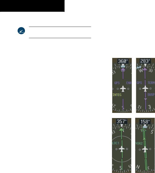
Navigation Source
NOTE:OBS is only available with the active flight plan leg, when navigating under GPS.
The HSI can display two sources of navigation, GPS or NAV (VOR, localizer, and glideslope). In GPS mode, the flight plan legs are sequenced automatically. Enabling OBS mode suspends auto sequencing of waypoints, but retains the current “active-to” waypoint as the navigation reference, even after the waypoint is passed. When OBS is disabled, the GPS returns to normal operation, with automatic sequencing of waypoints. OBS mode also allows the pilot to set the desired course TO/FROM a waypoint.
Color indicates the current navigation source: magenta (GPS ) or green (VOR and LOC). As the user crosses the MAP, “SUSP” appears on the HSI in place of OBS and the OBS softkey now reads “SUSP”, indicating that automatic sequencing of approach waypoints is suspended at the MAP. The following yellow annunciations may appear on the HSI:
•INTEG – RAIM not available
•WARN – GPS detects position error
To change between navigation sources:
1.Press the CDI softkey to change from GPS to VOR1 or LOC1. This places the cyan tuning box over the NAV1 standby frequency in the upper left corner of the PFD.
2.Press the CDI softkey again to change from VOR1 or LOC1 to VOR2 or LOC2. This places the cyan tuning box over the NAV2 standby frequency.
3.Press the CDI softkey a third time to return to GPS.
To enable/disable OBS mode while navigating with GPS:
1.Press the OBS softkey to select OBS Mode.
2.Turn the small CRS knob to select the desired course TO/FROM the waypoint.
3.Press the OBSsoftkey again to return to normal operation.
Figure 2-32 GPS INTEG, GPS SUSP, LOC1 and VOR2
2-20 |
Garmin G1000 Pilot’s Guide for Cessna Nav III |
190-00498-00 Rev.A |