

- •1.1 System Description
- •1.2 Line Replaceable Units
- •1.3 PFD/MFD Controls
- •1.4 Secure Digital Cards
- •1.5 System Power-up
- •1.6 Display Backlighting
- •1.7 System Operation
- •Normal Mode
- •Reversionary Mode
- •AHRS Operation
- •2.1 Introduction
- •2.2 Backlighting
- •2.3 Softkey Function
- •2.4 Flight Instruments
- •Airspeed Indicator
- •Attitude Indicator
- •Altimeter
- •Vertical Speed Indicator
- •Horizontal Situation Indicator
- •Communication Frequency Window
- •Navigation Frequency Window
- •Navigation Status Bar
- •Transponder Status Bar
- •2.6 Supplemental Flight Data
- •Outside Air Temperature Box
- •System Time Box
- •Traffic Annunciation
- •Terrain Proximity
- •Terrain Awareness and Warning System (TAWS) (Optional)
- •Inset Map
- •Working with Menus
- •Auxiliary Window Keys
- •Auxiliary Windows
- •2.7 Reversionary Mode
- •2.8 Alerts and Annunciations
- •Alerts Window
- •Annunciation Window
- •Softkey Annunciations
- •3.1 Overview
- •Windows and Fields
- •Radio Selection
- •Controls
- •Tuning Box
- •Switching Between Radios
- •Manually Tuning a Frequency
- •Radio Indicators
- •Volume
- •Frequency Transfer Arrow
- •3.2 COM Operation
- •Frequency Spacing
- •Automatic Squelch
- •Selecting a COM Radio
- •Emergency Frequency (121.500 MHz)
- •Quick-Tuning and Activating 121.500 MHz
- •Stuck Microphone
- •3.3 NAV Operation
- •Frequency Range
- •Morse Code Identifier
- •NAV Radio Selection for Navigation
- •ADF/DME Tuning
- •DME Tuning
- •3.4 Frequency Auto-tuning
- •Auto-tuning on the PFD
- •Auto-tuning on the MFD
- •Auto-Tuning on Approach Activation (NAV Frequencies)
- •4.1 Transponder Description
- •Transponder Softkeys
- •Transponder Status Bar
- •Mode S Features
- •Traffic Information Service (TIS)
- •4.2 Operation
- •Mode Selection
- •Code Selection
- •IDENT Function
- •5.1 Audio Panel Description
- •Transceivers
- •Mono/Stereo Headsets
- •Unmuted/Unswitched Inputs
- •Front Panel Controls
- •5.2 Operation
- •Power-up and Fail-safe Operation
- •Key Annunciators
- •Lighting
- •Transceiver Keys
- •Optional COM Muting
- •Split COM Function
- •PA Function
- •Speaker
- •Marker Beacon Receiver
- •Marker Beacon Volume Adjustment
- •Navigation Radios
- •Intercom System (ICS) Isolation
- •Intercom Volume and Squelch
- •Entertainment Inputs
- •GDL 69/69A XM Radio System
- •Master Avionics Squelch (MASQ)
- •Digital Clearance Recorder with Playback Capability
- •Reversionary Mode
- •6.1 Introduction
- •EIS Pages
- •EIS Indicators
- •EiS Page Reversion
- •6.2 Engine Page
- •6.3 Lean Page
- •6.4 System Page
- •7.1 Introduction
- •Description
- •Reversionary Mode
- •Optional Equipment
- •MFD Power-up
- •MFD Backlighting
- •MFD Softkeys
- •Electronic Checklists (optional)
- •MFD Page Groups
- •Working With Menus
- •7.2 Navigation Map Page
- •Navigation Map Page Operations
- •7.3 Traffic Map Page
- •TIS Symbology
- •Traffic Map Page Operations
- •7.4 Terrain Proximity Page
- •Terrain Proximity Page Operations
- •Displaying Obstacle Data
- •Navigation Map Display Conditions
- •Displaying Terrain on the TAWS Page
- •7.6 Direct-to Navigation
- •Direct-to Navigation Operations
- •7.7 Flight Plans
- •Active Flight Plan Page
- •Active Flight Plan Page Options
- •Flight Plan Catalog Page
- •Flight Plan Catalog Page Operations
- •Vertical Navigation (VNAV) Page
- •7.8 Procedures
- •Arrivals and Departures
- •Approaches
- •G1000 Navigational Guidance for Approaches
- •Selecting Approaches
- •7.9 Waypoint Page Group
- •AIRPORT Information Page (INFO)
- •Airport Frequency Information Field
- •AIRPORT Information Page Options
- •Departure Information Page (DP)
- •Arrival Information Page (STAR)
- •Approach Information Page
- •Intersection Information Page
- •NDB Information Page
- •VOR Information Page
- •User Waypoint Information Page
- •Creating User Waypoints
- •Modifying User Waypoints
- •User Waypoint Information Page Options
- •7.10 Auxiliary Page Group
- •Trip Planning Page
- •GPS Status Page
- •System Setup Page
- •System Status Page
- •7.11 Nearest Page Group
- •Navigating to a Nearest Waypoint
- •Nearest Intersections Page
- •Nearest NDB Page
- •Nearest VOR Page
- •Nearest User Waypoint Page
- •Nearest Frequencies Page
- •Nearest Airspaces Page
- •8.1 Introduction
- •8.2 WX-500 Stormscope
- •Displaying Stormscope Lightning Data on the Navigation Map Page
- •Stormscope Page
- •8.3 Traffic Advisory System
- •Displaying and Configuring TAS Traffic on the Navigation Map Page
- •Traffic Map Page
- •Failure Response
- •Description of Traffic Advisory Criteria
- •User-Initiated Test
- •TAS Voice Announcements
- •Switching Between Standby and Various Operating Modes
- •Altitude Display Mode
- •Traffic Map Page Display Range
- •8.4 XM Weather and XM Radio
- •Introduction
- •XM Weather
- •Weather Product Symbols
- •XM Digital Audio Entertainment
- •XM Radio Page
- •9.1 Introduction
- •9.2 Alert Level Definitions
- •9.4 CO Guardian Messages
- •9.6 G1000 System Annunciations
- •Appendices
- •Aviation Database
- •Terrain and Obstacle Databases
- •Introduction
- •TIS vs. TCAS
- •TIS Limitations
- •Airport
- •NAVAIDS
- •Basemap
- •Traffic
- •Lightning Strike
- •Impact Points (TAWS Only)
- •Miscellaneous
- •Line Symbols
- •Obstacle database
- •Terrain Color Chart
- •GMA 1347 Audio Panel
- •GIA 63 Integrated Avionics Units
- •GDC 74A Air Data Computer
- •GTX 33 Mode S Transponder
- •GEA 71 Engine/Airframe Unit
- •GDL 69/69A Weather Data Link
- •GRS 77 AHRS
- •Index

8.3 TRAFFIC ADVISORY SYSTEM
TheG1000providesanoptionaldisplayinterfaceforthe
Bendix King KTA870 Traffic Advisory System.
NOTE: This document assumes the user has experience operating the G1000 Multi Function Display and is familiar with the KTA870 Pilot’s Guide.
NOTE: This section describes the G1000 for TAS only. The G1000 Multi Function Display document describes the standard TIS interface.
DISPLAYING AND CONFIGURING TAS TRAFFIC ON THE NAVIGATION MAP PAGE
The display of TAS traffic on the Navigation Map Page is designed to closely resemble the display symbology used on the SKYWATCH. TAS Traffic is only displayed on the Navigation Map Page if aircraft heading data is available. When heading is not available, Traffic Advisories are displayed as non-bearing banners on the Navigation Map Page.
To display TAS traffic on the Navigation Map Page:
1.Select the Navigation Map Page, press the MAP softkey, then press the TRAFFIC softkey
OPTIONAL EQUIPMENT
To configure TAS traffic on the
Navigation Map Page:
1.Select the Navigation Map Page.
2.Press MENU to display the Page Menu.Turn the small right knob to select ‘Map Setup’ and press the ENT key.
3.The flashing cursor highlights the ‘GROUP’ field. Turn the small FMS knob to select Traffic and press ENT.
4.Turn the large FMS knob to select the desired Traffic Mode option.Turn the small FMS knob to select the desired option and press the ENT key. Repeat the step for Traffic Symbol and Traffic Label.
5.Return to the Map Page by pressing the FMS knob or momentarily pressing and holding the CLR key.
Traffic mode allows the pilot to choose which traffic is displayed (all traffic, traffic and proximity advisories, or traffic advisories only).
•Traffic Advisories (TA)—Solid Yellow Circles
•Proximity Advisories (PA)—Solid White Diamonds
•Other—Hollow White Diamonds
Proximity Advisories (PA) are displayed as solid white diamonds (SKYWATCH shows these PAs as hollow diamonds since the SKYWATCH display is monochrome). PAs are defined as traffic within the 5.0-nm range, within
± 1200 ft. of altitude separation, and are not a traffic advisory (TA).
190-00498-00 Rev.A |
Garmin G1000 Pilot’s Guide for Cessna Nav III |
8-7 |
OPTIONAL EQUIPMENT
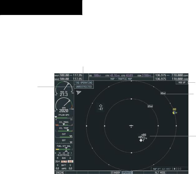
TRAFFIC MAP PAGE
Operating Mode Indicator
Altitude
Display Mode
Indicator
Figure 8-6 Traffic Map Page
Heading Indicator
Traffic Display
Range
Traffic
8-8 |
Garmin G1000 Pilot’s Guide for Cessna Nav III |
190-00498-00 Rev.A |

The Traffic Map Page (Figure 8-6) controls the source of TAS traffic data on the Navigation Map Page. NOTE:
When the G1000 is configured for TAS, the system only receives TAS traffic. Otherwise, if TAS is not configured, the system provides TIS traffic data.
To select the Traffic Map Page:
1.Turn the large FMS knob until the Map Page group is selected.
2.Turn the small FMS knob until the Traffic Map page is selected.
FAILURE RESPONSE
Errors indicated by a FAILED screen prevent continued use of the KTA 870 interface. See the KTA 870 Pilot’s Guide for detailed information on Failure Response.
DESCRIPTION OF TRAFFIC ADVISORY CRITERIA
For a description of Traffic Advisory System criteria and display interpretation refer to the KTA 870 Pilot’s Guide.
OPTIONAL EQUIPMENT
USER-INITIATED TEST
NOTE:A user initiated test can only be performed when the system is in standby or failed mode.
To perform a user-initiated test:
1.Press the TESTsoftkey or use the menu to select ‘Test Mode’. Self-test is best accomplished with the range set to 2 and 6 nm, and will last approximately 8 seconds. The following is displayed when a user-initiated test is performed:
•A Traffic Advisory (yellow circle) appears at 9 o’clock, range of 2 miles, 200 feet below and climbing.
•Proximity Traffic (solid white diamond) appears at 1 o’clock, range 3.6 miles, 1000 feet below, descending.
•Non-Threat traffic (open white diamond) appears at 11 o’clock, range of 3.6. miles, flying level 1000 feet above.
190-00498-00 Rev.A |
Garmin G1000 Pilot’s Guide for Cessna Nav III |
8-9 |

OPTIONAL EQUIPMENT
If the KTA 870 successfully completes self-test, a synthesized voice announces: “TAS SYSTEM OK”. The unit should switch to OPERATE mode at the completion of the test. Should a failure be detected during self-test, the audio message says: “TAS SYSTEM FAIL”. The unit should revert back to STANDBY mode if a self-test failure is detected.
TAS VOICE ANNOUNCEMENTS
See the KTA 870 Pilot’s Guide for information on voice announcements.
To begin tracking intruder aircraft:
Press the OPERATE softkey.
SWITCHING BETWEEN STANDBY AND VARIOUS OPERATING MODES
The unit must be in operating mode for traffic to be displayed. The ability to switch out of standby into operating mode on the ground is especially useful for scanning the airspace around the airport before takeoff.
To switch into Operating Mode from Standby Mode:
1.Press the OPERATE softkey or menu‘Operating Mode’.
2.If ‘Operating Mode’ is selected from the FMS menu, press the ENT key to confirm and place the KTA 870/KMH 880 in operating mode.
To switch into Standby Mode from the Traffic Page:
Press the STANDBY softkey.
ALTITUDE DISPLAY MODE
To change the Altitude Display Mode:
1.Press the ALT MODE softkey then press one of the following options: BELOW, NORMAL,ABOVE, UNREST.
With each selection, the screen changes to display the traffic detected within the selected altitude display range. The G1000 screen also displays unrestricted traffic (UNREST) having a range of maximum specified by the KTA 870 Pilot’s Guide. Refer to the KTA 870 Pilot’s Guide for information regarding altitude display ranges. Note that confirmation is not required. The mode is changed immediately when selected.
TRAFFIC MAP PAGE DISPLAY RANGE
The pilot can change the display range on the Traffic Map Page at any time.
To change the display range on the Traffic Page:
1.Turn the RNG knob to zoom through the following range options:
•Bendix/King KTA 870—2 nm, 2 and 6 nm, 6 and 12 nm, 12 and 24 nm, and 24 and 40 nm.
8-10 |
Garmin G1000 Pilot’s Guide for Cessna Nav III |
190-00498-00 Rev.A |