

Добавил:
AlexCPL
Опубликованный материал нарушает ваши авторские права? Сообщите нам.
Вуз:
Предмет:
Файл:G1000_CessnaNavIII_PilotsGuide.pdf
X
- •1.1 System Description
- •1.2 Line Replaceable Units
- •1.3 PFD/MFD Controls
- •1.4 Secure Digital Cards
- •1.5 System Power-up
- •1.6 Display Backlighting
- •1.7 System Operation
- •Normal Mode
- •Reversionary Mode
- •AHRS Operation
- •2.1 Introduction
- •2.2 Backlighting
- •2.3 Softkey Function
- •2.4 Flight Instruments
- •Airspeed Indicator
- •Attitude Indicator
- •Altimeter
- •Vertical Speed Indicator
- •Horizontal Situation Indicator
- •Communication Frequency Window
- •Navigation Frequency Window
- •Navigation Status Bar
- •Transponder Status Bar
- •2.6 Supplemental Flight Data
- •Outside Air Temperature Box
- •System Time Box
- •Traffic Annunciation
- •Terrain Proximity
- •Terrain Awareness and Warning System (TAWS) (Optional)
- •Inset Map
- •Working with Menus
- •Auxiliary Window Keys
- •Auxiliary Windows
- •2.7 Reversionary Mode
- •2.8 Alerts and Annunciations
- •Alerts Window
- •Annunciation Window
- •Softkey Annunciations
- •3.1 Overview
- •Windows and Fields
- •Radio Selection
- •Controls
- •Tuning Box
- •Switching Between Radios
- •Manually Tuning a Frequency
- •Radio Indicators
- •Volume
- •Frequency Transfer Arrow
- •3.2 COM Operation
- •Frequency Spacing
- •Automatic Squelch
- •Selecting a COM Radio
- •Emergency Frequency (121.500 MHz)
- •Quick-Tuning and Activating 121.500 MHz
- •Stuck Microphone
- •3.3 NAV Operation
- •Frequency Range
- •Morse Code Identifier
- •NAV Radio Selection for Navigation
- •ADF/DME Tuning
- •DME Tuning
- •3.4 Frequency Auto-tuning
- •Auto-tuning on the PFD
- •Auto-tuning on the MFD
- •Auto-Tuning on Approach Activation (NAV Frequencies)
- •4.1 Transponder Description
- •Transponder Softkeys
- •Transponder Status Bar
- •Mode S Features
- •Traffic Information Service (TIS)
- •4.2 Operation
- •Mode Selection
- •Code Selection
- •IDENT Function
- •5.1 Audio Panel Description
- •Transceivers
- •Mono/Stereo Headsets
- •Unmuted/Unswitched Inputs
- •Front Panel Controls
- •5.2 Operation
- •Power-up and Fail-safe Operation
- •Key Annunciators
- •Lighting
- •Transceiver Keys
- •Optional COM Muting
- •Split COM Function
- •PA Function
- •Speaker
- •Marker Beacon Receiver
- •Marker Beacon Volume Adjustment
- •Navigation Radios
- •Intercom System (ICS) Isolation
- •Intercom Volume and Squelch
- •Entertainment Inputs
- •GDL 69/69A XM Radio System
- •Master Avionics Squelch (MASQ)
- •Digital Clearance Recorder with Playback Capability
- •Reversionary Mode
- •6.1 Introduction
- •EIS Pages
- •EIS Indicators
- •EiS Page Reversion
- •6.2 Engine Page
- •6.3 Lean Page
- •6.4 System Page
- •7.1 Introduction
- •Description
- •Reversionary Mode
- •Optional Equipment
- •MFD Power-up
- •MFD Backlighting
- •MFD Softkeys
- •Electronic Checklists (optional)
- •MFD Page Groups
- •Working With Menus
- •7.2 Navigation Map Page
- •Navigation Map Page Operations
- •7.3 Traffic Map Page
- •TIS Symbology
- •Traffic Map Page Operations
- •7.4 Terrain Proximity Page
- •Terrain Proximity Page Operations
- •Displaying Obstacle Data
- •Navigation Map Display Conditions
- •Displaying Terrain on the TAWS Page
- •7.6 Direct-to Navigation
- •Direct-to Navigation Operations
- •7.7 Flight Plans
- •Active Flight Plan Page
- •Active Flight Plan Page Options
- •Flight Plan Catalog Page
- •Flight Plan Catalog Page Operations
- •Vertical Navigation (VNAV) Page
- •7.8 Procedures
- •Arrivals and Departures
- •Approaches
- •G1000 Navigational Guidance for Approaches
- •Selecting Approaches
- •7.9 Waypoint Page Group
- •AIRPORT Information Page (INFO)
- •Airport Frequency Information Field
- •AIRPORT Information Page Options
- •Departure Information Page (DP)
- •Arrival Information Page (STAR)
- •Approach Information Page
- •Intersection Information Page
- •NDB Information Page
- •VOR Information Page
- •User Waypoint Information Page
- •Creating User Waypoints
- •Modifying User Waypoints
- •User Waypoint Information Page Options
- •7.10 Auxiliary Page Group
- •Trip Planning Page
- •GPS Status Page
- •System Setup Page
- •System Status Page
- •7.11 Nearest Page Group
- •Navigating to a Nearest Waypoint
- •Nearest Intersections Page
- •Nearest NDB Page
- •Nearest VOR Page
- •Nearest User Waypoint Page
- •Nearest Frequencies Page
- •Nearest Airspaces Page
- •8.1 Introduction
- •8.2 WX-500 Stormscope
- •Displaying Stormscope Lightning Data on the Navigation Map Page
- •Stormscope Page
- •8.3 Traffic Advisory System
- •Displaying and Configuring TAS Traffic on the Navigation Map Page
- •Traffic Map Page
- •Failure Response
- •Description of Traffic Advisory Criteria
- •User-Initiated Test
- •TAS Voice Announcements
- •Switching Between Standby and Various Operating Modes
- •Altitude Display Mode
- •Traffic Map Page Display Range
- •8.4 XM Weather and XM Radio
- •Introduction
- •XM Weather
- •Weather Product Symbols
- •XM Digital Audio Entertainment
- •XM Radio Page
- •9.1 Introduction
- •9.2 Alert Level Definitions
- •9.4 CO Guardian Messages
- •9.6 G1000 System Annunciations
- •Appendices
- •Aviation Database
- •Terrain and Obstacle Databases
- •Introduction
- •TIS vs. TCAS
- •TIS Limitations
- •Airport
- •NAVAIDS
- •Basemap
- •Traffic
- •Lightning Strike
- •Impact Points (TAWS Only)
- •Miscellaneous
- •Line Symbols
- •Obstacle database
- •Terrain Color Chart
- •GMA 1347 Audio Panel
- •GIA 63 Integrated Avionics Units
- •GDC 74A Air Data Computer
- •GTX 33 Mode S Transponder
- •GEA 71 Engine/Airframe Unit
- •GDL 69/69A Weather Data Link
- •GRS 77 AHRS
- •Index
MULTI FUNCTION DISPLAY
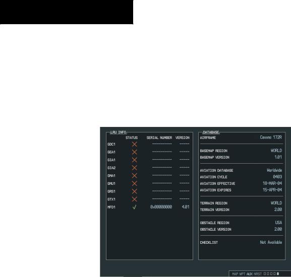
SYSTEM STATUS PAGE
The System Status Page displays the status and software version numbers for all detected system LRUs. Pertinent information of all databases in the system is also displayed. Active LRUs are indicated by a green check mark and failed LRUs are indicated by a red X. The Pilot should note the failed LRU and inform a Cessna service center or Garmin dealer.
Figure 7-82 System Status Page
7-124 |
Garmin G1000 Pilot’s Guide for Cessna Nav III |
190-00498-00 Rev.A |
Соседние файлы в предмете [НЕСОРТИРОВАННОЕ]