

- •1.1 System Description
- •1.2 Line Replaceable Units
- •1.3 PFD/MFD Controls
- •1.4 Secure Digital Cards
- •1.5 System Power-up
- •1.6 Display Backlighting
- •1.7 System Operation
- •Normal Mode
- •Reversionary Mode
- •AHRS Operation
- •2.1 Introduction
- •2.2 Backlighting
- •2.3 Softkey Function
- •2.4 Flight Instruments
- •Airspeed Indicator
- •Attitude Indicator
- •Altimeter
- •Vertical Speed Indicator
- •Horizontal Situation Indicator
- •Communication Frequency Window
- •Navigation Frequency Window
- •Navigation Status Bar
- •Transponder Status Bar
- •2.6 Supplemental Flight Data
- •Outside Air Temperature Box
- •System Time Box
- •Traffic Annunciation
- •Terrain Proximity
- •Terrain Awareness and Warning System (TAWS) (Optional)
- •Inset Map
- •Working with Menus
- •Auxiliary Window Keys
- •Auxiliary Windows
- •2.7 Reversionary Mode
- •2.8 Alerts and Annunciations
- •Alerts Window
- •Annunciation Window
- •Softkey Annunciations
- •3.1 Overview
- •Windows and Fields
- •Radio Selection
- •Controls
- •Tuning Box
- •Switching Between Radios
- •Manually Tuning a Frequency
- •Radio Indicators
- •Volume
- •Frequency Transfer Arrow
- •3.2 COM Operation
- •Frequency Spacing
- •Automatic Squelch
- •Selecting a COM Radio
- •Emergency Frequency (121.500 MHz)
- •Quick-Tuning and Activating 121.500 MHz
- •Stuck Microphone
- •3.3 NAV Operation
- •Frequency Range
- •Morse Code Identifier
- •NAV Radio Selection for Navigation
- •ADF/DME Tuning
- •DME Tuning
- •3.4 Frequency Auto-tuning
- •Auto-tuning on the PFD
- •Auto-tuning on the MFD
- •Auto-Tuning on Approach Activation (NAV Frequencies)
- •4.1 Transponder Description
- •Transponder Softkeys
- •Transponder Status Bar
- •Mode S Features
- •Traffic Information Service (TIS)
- •4.2 Operation
- •Mode Selection
- •Code Selection
- •IDENT Function
- •5.1 Audio Panel Description
- •Transceivers
- •Mono/Stereo Headsets
- •Unmuted/Unswitched Inputs
- •Front Panel Controls
- •5.2 Operation
- •Power-up and Fail-safe Operation
- •Key Annunciators
- •Lighting
- •Transceiver Keys
- •Optional COM Muting
- •Split COM Function
- •PA Function
- •Speaker
- •Marker Beacon Receiver
- •Marker Beacon Volume Adjustment
- •Navigation Radios
- •Intercom System (ICS) Isolation
- •Intercom Volume and Squelch
- •Entertainment Inputs
- •GDL 69/69A XM Radio System
- •Master Avionics Squelch (MASQ)
- •Digital Clearance Recorder with Playback Capability
- •Reversionary Mode
- •6.1 Introduction
- •EIS Pages
- •EIS Indicators
- •EiS Page Reversion
- •6.2 Engine Page
- •6.3 Lean Page
- •6.4 System Page
- •7.1 Introduction
- •Description
- •Reversionary Mode
- •Optional Equipment
- •MFD Power-up
- •MFD Backlighting
- •MFD Softkeys
- •Electronic Checklists (optional)
- •MFD Page Groups
- •Working With Menus
- •7.2 Navigation Map Page
- •Navigation Map Page Operations
- •7.3 Traffic Map Page
- •TIS Symbology
- •Traffic Map Page Operations
- •7.4 Terrain Proximity Page
- •Terrain Proximity Page Operations
- •Displaying Obstacle Data
- •Navigation Map Display Conditions
- •Displaying Terrain on the TAWS Page
- •7.6 Direct-to Navigation
- •Direct-to Navigation Operations
- •7.7 Flight Plans
- •Active Flight Plan Page
- •Active Flight Plan Page Options
- •Flight Plan Catalog Page
- •Flight Plan Catalog Page Operations
- •Vertical Navigation (VNAV) Page
- •7.8 Procedures
- •Arrivals and Departures
- •Approaches
- •G1000 Navigational Guidance for Approaches
- •Selecting Approaches
- •7.9 Waypoint Page Group
- •AIRPORT Information Page (INFO)
- •Airport Frequency Information Field
- •AIRPORT Information Page Options
- •Departure Information Page (DP)
- •Arrival Information Page (STAR)
- •Approach Information Page
- •Intersection Information Page
- •NDB Information Page
- •VOR Information Page
- •User Waypoint Information Page
- •Creating User Waypoints
- •Modifying User Waypoints
- •User Waypoint Information Page Options
- •7.10 Auxiliary Page Group
- •Trip Planning Page
- •GPS Status Page
- •System Setup Page
- •System Status Page
- •7.11 Nearest Page Group
- •Navigating to a Nearest Waypoint
- •Nearest Intersections Page
- •Nearest NDB Page
- •Nearest VOR Page
- •Nearest User Waypoint Page
- •Nearest Frequencies Page
- •Nearest Airspaces Page
- •8.1 Introduction
- •8.2 WX-500 Stormscope
- •Displaying Stormscope Lightning Data on the Navigation Map Page
- •Stormscope Page
- •8.3 Traffic Advisory System
- •Displaying and Configuring TAS Traffic on the Navigation Map Page
- •Traffic Map Page
- •Failure Response
- •Description of Traffic Advisory Criteria
- •User-Initiated Test
- •TAS Voice Announcements
- •Switching Between Standby and Various Operating Modes
- •Altitude Display Mode
- •Traffic Map Page Display Range
- •8.4 XM Weather and XM Radio
- •Introduction
- •XM Weather
- •Weather Product Symbols
- •XM Digital Audio Entertainment
- •XM Radio Page
- •9.1 Introduction
- •9.2 Alert Level Definitions
- •9.4 CO Guardian Messages
- •9.6 G1000 System Annunciations
- •Appendices
- •Aviation Database
- •Terrain and Obstacle Databases
- •Introduction
- •TIS vs. TCAS
- •TIS Limitations
- •Airport
- •NAVAIDS
- •Basemap
- •Traffic
- •Lightning Strike
- •Impact Points (TAWS Only)
- •Miscellaneous
- •Line Symbols
- •Obstacle database
- •Terrain Color Chart
- •GMA 1347 Audio Panel
- •GIA 63 Integrated Avionics Units
- •GDC 74A Air Data Computer
- •GTX 33 Mode S Transponder
- •GEA 71 Engine/Airframe Unit
- •GDL 69/69A Weather Data Link
- •GRS 77 AHRS
- •Index
MULTI FUNCTION DISPLAY
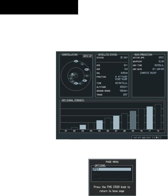
GPS STATUS PAGE
The GPS Status Page provides a visual reference of GPS receiver functions:
Figure 7-77 GPS Status Page
Figure 7-78 GPS Status Page Menu
7-112 |
Garmin G1000 Pilot’s Guide for Cessna Nav III |
190-00498-00 Rev.A |

Satellite Status Page
•Satellite constellation displaying the following for each satellite being tracked:
Azimuth Elevation PRN number Tracking status
•A receiver tracking status display that displays the following GPS sub-system status situations:
‘2D NAV’, when only 2-dimensional position is available
‘3D NAV’, when 3-dimensional position is available
•Estimated position error
•Dilution of precision
•Horizontal uncertainty level
•GPS calculated position
•GPS calculated time of day
•GPS calculated altitude
•Ground Speed
•Track
MULTI FUNCTION DISPLAY
The sky view display at the top left corner of the page shows the satellites currently in view as well as their respective positions. The outer circle of the sky view represents the horizon (with north at the top of the circle); the inner circle represents 45° above the horizon and the center point shows the position directly overhead. Each satellite has a 30-second data transmission that must be collected (hollow signal strength bar) before the satellite may be used for navigation (solid signal strength bar). Once the GPS receiver has determined your position, the G1000 indicates your position, altitude, track and ground speed. The GPS receiver status field also displays the following messages under the appropriate conditions:
•Acquiring Sat - The GPS receiver is acquiring satellites for navigation. In this mode, the receiver uses satellite orbital data (collected continuously from the satellites) and last known position to determine the satellites that should be in view.
•2D Navigation - The GPS receiver is in 2D navigation mode.
•3D Navigation - The GPS receiver is in 3D navigation mode and computes altitude using satellite data.
190-00498-00 Rev.A |
Garmin G1000 Pilot’s Guide for Cessna Nav III |
7-113 |

MULTI FUNCTION DISPLAY
The Satellite Status Page also indicates the accuracy of the position fix, using Estimated Position Error (EPE) and Dilution of Precision (DOP) figures. DOP measures satellite geometry quality (i.e., number of satellites received and where they are relative to each other) on a range from 0.0 to 9.9. The lowest numbers are the best accuracy and the highest numbers are the worst. EPE uses DOP and other factors to calculate a horizontal position error, in feet or meters.
RAIM Prediction
“RAIM” is an acronym for Receiver Autonomous IntegrityMonitoring,aGPSreceiverfunctionthatperforms a consistency check on all tracked satellites. RAIM ensures that the available satellite geometry will allow the receiver to calculate a position within a specified protection limit (2.0 nautical miles for oceanic and en route, 1.0 NM for terminal and 0.3 NM for non-precision approaches). During oceanic, en-route, and terminal phases of flight, RAIM is available nearly 100% of the time.
Because of the tighter protection limit on approaches, there may be times when RAIM is not available. The G1000 automatically monitors RAIM and warns you with an alert message when it is not available. If RAIM is not available when crossing the FAF, the pilot must fly the missed approach procedure.
The RAIM prediction function also indicates whether RAIM will be available for a specified date and time. If RAIM is not predicted to be available for the final approach course, the approach does not become active
— as indicated by an “Approach is not active” message, and a “RAIM not available from FAF to MAP” message.
To predict RAIM availability:
1.Select the GPS Status Page.
2.Press the FMS knob. Turn the small and large
FMS knobs to select the ‘WAYPOINT’ field.
3.Turn the small FMS knob to display the Waypoint Information Page.
4.Turn the small and large FMS knobs to enter the desired waypoint. Press the ENT key to accept.
5.Turn the small and large FMS knobs to enter an arrival time and press the ENT key.
6.Turn the small and large FMS knob to enter an arrival date.
7.The cursor highlights the ‘COMPUTE RAIM’ field. Press the ENT key to compute RAIM.The following options are displayed:
•‘COMPUTE RAIM?’ if RAIM has not been computed for the current waypoint, time, and date combination
•‘COMPUTING AVAILABILITY’ if the RAIM calculation is in progress
•‘RAIM AVAILABLE’ if RAIM is predicted to be available for the given combination of waypoint, time, and date
•‘RAIM NOT AVAILABLE’ if RAIM is predicted to be unavailable for the given combination of waypoint, time, and date
NOTE: RAIM computations predict satellite coverage within +/- 15 minutes of the specified arrival date and time.
7-114 |
Garmin G1000 Pilot’s Guide for Cessna Nav III |
190-00498-00 Rev.A |
Figure 7-79 RAIM
GPS Signal Strength
The Satellite Status Page can be helpful in troubleshootingweak(ormissing)signallevelsduetopoor satellite coverage or installation problems. Refer to this page occasionally to monitor GPS receiver performance and establish a normal pattern for system operation. Should problems occur at a later date, it may be helpful to have an established baseline from which to compare.
MULTI FUNCTION DISPLAY
As the GPS receiver locks onto satellites, a signal strength bar is displayed for each satellite in view, with the appropriate satellite number (01-32) underneath each bar. The progress of satellite acquisition is shown in three stages:
•No signal strength bars - the receiver is looking for the satellites indicated.
•Hollow signal strength bars - the receiver has found the satellites and is collecting data.
•Solid signal strength bars - the receiver has collected the necessary data and the satellites are ready for use.
•Checkered signal strength bars - the receiver has excluded the satellite (FDE).
Figure 7-80 GPS Signal Strength
190-00498-00 Rev.A |
Garmin G1000 Pilot’s Guide for Cessna Nav III |
7-115 |