

6.1 INTRODUCTION
The G1000 Engine Indication System (EIS) provides the flight crew with gauges, bar graphs, and numeric readouts of engine parameters. The EIS is displayed on the left side of the MFD during normal operations. In reversionary mode, the GDUs are re-configured to present PFDsymbologytogetherwiththeEIS(theEISisdisplayed on the left side).
NOTE:Refer to the System Overview for information regarding reversionary mode.
EIS PAGES
The EIS has information on three pages, which are accessed using the ENGINE softkey:
•Engine Page – This is the default page, which displaysallcriticalengine,fuel,andelectricalinformation.
•Lean Page – This page provides engine leaning information and a user interface to perform engine leaning.
•SystemPage–Thispagedisplaysanumericreadout for the critical engine, fuel and electrical indicators.
EIS INDICATORS
The EIS Pages display engine information using round dial gauges, horizontal bar indicators, bar graphs (see Lean Page), and digital readouts:
NOTE: All EIS pages show the gauge(s), Fuel Quantity Indicator, and fuel flow.
ENGINE INDICATION SYSTEM
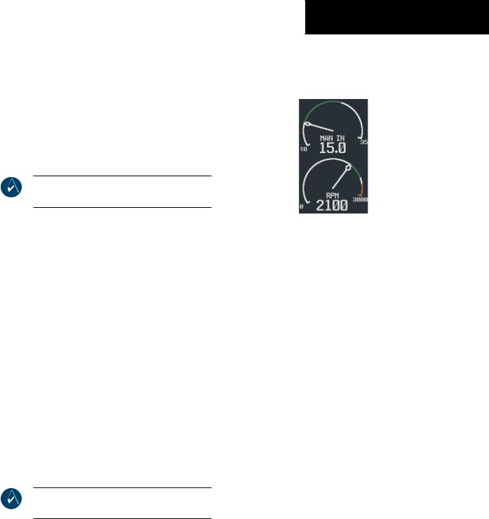
Round Dial Gauges
The gauges are color-coded and have a white pointer. A white digital readout appears beneath the gauge.
Figure 6-1 Round Dial Gauges: Manifold
Pressure Gauge and Tachometer
Tachometer (RPM)
The tachometer is displayed as a round dial gauge near the top of the page. Propeller speed is shown in revolutions per minute (RPM).
Colors along the arc of the gauge represent:
•White (low RPM) – Below normal flight operating range
•Green – Normal flight operating range
•White(highRPM)–Above normalflightoperating range (Models 206 and T206)
•Red – Propeller overspeed
Manifold Pressure Gauge (MAN IN) - Models 182,T182,
206,T206
The Manifold Pressure gauge displays the engine power in inches of mercury (in Hg). A white tick mark is displayed indicating the cruise manifold pressure (Model T182 only).
190-00498-00 Rev.A |
Garmin G1000 Pilot’s Guide for Cessna Nav III |
6-1 |
ENGINE INDICATION SYSTEM
Colors along the arc of the gauge represent:
•White(lowpressures)–Belownormaloperatingrange
•Green – Normal operating range
•White (high pressures) – Above normal operating range
•Red– Maximum manifold pressure (turbocharged)
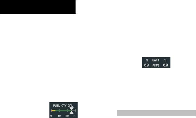
Horizontal Bar Indicators
These indicators are color-coded and have triangular pointers. Pointers appear in white to indicate operation within the acceptable range. The pointer color changes to yellow or red when operating outside the normal range. Thegreenbandsonthehorizontalbarindicatorsrepresent normal ranges of operation.
Figure 6-2 Horizontal Bar Indicator: Fuel Quantity
Fuel Quantity (FUEL QTY GAL)
The Fuel Quantity Indicator displays the quantity of fuel in the tanks in gallons. The indicator ranges from 0 to F (full). Tick marks are at every 10 gallons, up to 30 gallons (20 gallons for the Model 172). Two pointers labeled L (left) and R (right) indicate the number of gallons in each fuel tank. When full, the indicator displays to 35 gallons per side (26 gallons for the Model 172).
•Green – Normal
•Yellow – Caution (low)
•Red – Warning
Digital Readouts
These readouts appear as white text on a black background, representing areas of normal operation. The color changes to black text on a yellow background (caution) or white text on a red background (warning) upon exceeding areas of normal operation.
Figure 6-3 Digital Readout:Ammeter
EIS PAGE REVERSION
The EIS automatically defaults back to the Engine Page from the Lean or System Page when any of the following parameters are exceeded:
Parameter |
Criterion |
|
Cylinder Head Temperature* |
> 500 ºF |
|
Oil Temperature |
> 245 ºF |
|
Oil Pressure |
< 20 PSI or |
|
> 120 PSI |
||
|
||
Battery Current |
< -1 A (discharge) |
|
(Main) |
||
|
||
Battery Current |
< 0 A (discharge) |
|
(Standby) |
||
|
||
Electrical Bus Voltage |
< 24.5 V or > 32.0 V |
|
(Main or Essential) |
||
|
||
Table 6-1 Engine Page Default Criteria |
||
Fluctuations in engine speed and fuel quantity above certain levels, depending on the airframe, also cause reversion back to the Engine Page.
(*) TheCylinderHeadTemperaturereversioncriterion does not apply to the Model 172.
6-2 |
Garmin G1000 Pilot’s Guide for Cessna Nav III |
190-00498-00 Rev.A |