

AUDIO PANEL
INTERCOM SYSTEM (ICS) ISOLATION
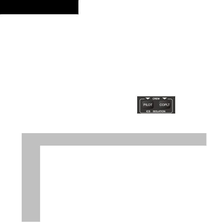
The intercom system (ICS) provides four (4) isolation modes: ALL, PILOT, COPILOT, and CREW. The desired mode can be selected or deselected using the PILOT and COPLT keys. The four (4) possible ICS isolation states are summarized in the table below.
PILOT Mode
PILOT isolation is selected when only the PILOT key annunciator is lit. In PILOT mode, the pilot can hear the selected radios. The copilot and passengers can communicate with each other.
COPILOT Mode
COPILOT isolation is selected when only the COPLT key annunciator is lit. In COPILOT mode, the copilot is isolated from the selected radios and everyone else. The pilot and passengers can hear the selected radios and communicate with each other.
CREW Mode
CREW mode is selected when both the PILOT and COPLT key annunciators are lit. In CREW mode, both the pilot and copilot can hear the selected radios and communicate with each other, while the passengers are isolated but can communicate with each other.
ALL Mode
ALLmodeisselectedwhenthePILOTandtheCOPLT key annunciators are not lit. In ALL mode, everyone hears the selected radios and is able to communicate with everyone else.
Figure 5-6 ICS Isolation Keys
|
Mode |
PILOT KEY |
COPLT KEY |
Pilot Hears |
Copilot Hears |
Passenger Hears |
|
|
ANNUNCIATOR |
ANNUNCIATOR |
|
||||
|
|
|
|
|
|
||
|
|
|
|
|
|
|
|
|
ALL |
|
|
Selected radios; |
Selected radios; |
Selected radios; |
|
|
OFF |
OFF |
pilot; copilot; |
pilot; copilot; |
pilot; copilot; |
|
|
|
|
|
|
passengers; MUSIC 1 |
passengers; MUSIC 1 |
passengers; MUSIC 2 |
|
|
|
|
|
|
|
|
|
|
PILOT |
|
|
Selected radios; |
Copilot; |
Copilot; |
|
|
ON |
OFF |
passengers; |
|
|||
|
pilot |
passengers; MUSIC 1 |
|
||||
|
|
|
|
MUSIC 2 |
|
||
|
|
|
|
|
|
|
|
|
|
|
|
|
|
|
|
|
COPILOT |
|
|
Selected radios; |
|
Selected radios; |
|
|
OFF |
ON |
pilot; passengers; |
Copilot |
pilot; passengers; |
|
|
|
|
|
|
MUSIC 1 |
|
MUSIC 2 |
|
|
|
|
|
|
|
|
|
|
CREW |
ON |
ON |
Selected radios; |
Selected radios; |
Passengers; |
|
|
pilot; copilot |
pilot; copilot |
MUSIC 2 |
|
|||
|
|
|
|
|
|||
|
|
|
|
|
|
|
|
|
|
|
Table 5-2 ICS Isolation Modes |
|
|
|
|
5-8 |
|
|
Garmin G1000 Pilot’s Guide for Cessna Nav III |
190-00498-00 Rev.A |
|||
INTERCOM VOLUME AND SQUELCH
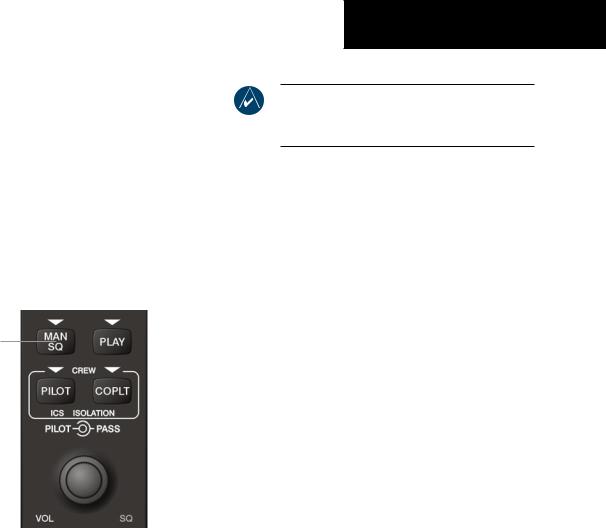
The MAN SQ key and VOL/SQ knob control the volume and squelch of the intercom. The MAN SQ key allows either automatic or manual control of the squelch setting. The VOL/SQ knob controls volume or manual squelch adjustment for the pilot and copilot/passenger.
When the SQ annunciator is not lit (auto-squelch is on), the VOL/SQ knob controls only the volume. When the SQ annunciator is lit (manual squelch), the VOL/SQ knob controls both volume and squelch.
Automatic/Manual
Squelch
Pilot |
|
|
|
|
|
|
|
Copilot |
|
|
|
|
|
|
|
|
|||
Volume |
|
|
|
|
|
|
|
|
Squelch |
|
|
|
|
|
|
|
|
||
|
|
Figure 5-7 Volume/Squelch Control |
|||||||
Intercom Volume Control
The intercom volume is controlled with the VOL/ SQ knob. The small knob controls the pilot volume. The large knob controls the copilot/passenger volume. Turning the knob clockwise increases volume, turning counterclockwise decreases volume. When squelch is automatic (MAN SQ annunciator is not lit) and the VOL annunciator at the bottom of the unit is lit, intercom volume may be adjusted.
AUDIO PANEL
NOTE: When the MAN SQ key is not lit (autosquelch is active),pressing the VOL/SQ knob has no effect on the VOL/SQ selection.
Intercom Manual Squelch Control
The intercom squelch function has the ability to quiet theambientcockpitnoisewhennopersonistalking. Each microphone input has an automatic squelch threshold. Manual squelch adjustment is also available if desired.
Pressing the MAN SQ key toggles between the automatic and manual squelch mode. When in manual squelch, the MAN SQ annunciator is lit.
In manual squelch mode the VOL/SQ knob adjusts either the volume or squelch threshold level.
Pressing the VOL/SQ knob toggles between volume andsquelchadjustment. Theannunciatoratthebottomof the unit indicates which function the knob is controlling.
In manual squelch mode, the small VOL/SQ knob controls pilot squelch threshold. The large VOL/SQ knob controls copilot/passenger squelch threshold. Turning either knob clockwise increases squelch level, counterclockwise decreases squelch.
ENTERTAINMENT INPUTS
The GMA 1347 provides two stereo auxiliary entertainment inputs; MUSIC 1 and MUSIC 2. These inputsarecompatiblewithpopularportableentertainment devices such as MP3 and CD players. Two 3.5 mm stereo phone jacks are installed in convenient locations for audio connection. The headphone outputs of the entertainment devices are plugged into the MUSIC 1 or MUSIC 2 jacks.
The current ICS isolation mode affects the distribution of the entertainment inputs MUSIC 1.
190-00498-00 Rev.A |
Garmin G1000 Pilot’s Guide for Cessna Nav III |
5-9 |
|
|

AUDIO PANEL
 NOTE: MUSIC 1 and MUSIC 2 cannot be completely turned off. Audio level for these inputs can be set above and below a nominal value. Contact a Garmin-authorized service center for adjustment.
MUSIC 1
MUSIC 1 can be heard by the pilot in COPILOT mode and in ALL mode, and can be heard by the copilot in PILOT mode and in ALL mode.
MUSIC 1 Muting
MUSIC 1 muting occurs when aircraft radio, marker beacon or ICS activity is heard. MUSIC 1 is always softmuted when an interruption occurs from an aircraft radio. SoftmutingisthegradualreturnofMUSIC1toitsoriginal volume level. The time required for MUSIC 1 volume to return at the headset outputs is between one-half and four seconds.
 NOTE: MUSIC 1 muting during ICS activity can be disabled. Contact a Garmin-authorized service center for details.
 NOTE: If the MKR/MUTE key is pressed and held for three (3) seconds, the GMA 1347 toggles music muting ON and OFF. When toggling, either one (1) or two (2) beeps can be heard; one (1) beep indicates that music muting is enabled, two (2) beeps indicate music muting is disabled.
MUSIC 2
MUSIC 2 can be heard only by the passengers and is never muted.
GDL 69/69A XM RADIO SYSTEM
When no external entertainment music is connected to the audio panel through MUSIC 1 and MUSIC 2 jacks, audio from the optional GDL 69A is heard by the pilot and passengers simultaneously.
Connecting a stereo input to either MUSIC 1 or MUSIC 2 removes the GDL 69A audio from that input. For example, if passengers prefer music while the pilot listens to the GDL 69A, the entertainment audio would be connected to the MUSIC 2 jack.
Refer to the Optional Equipment Section for more details on the GDL 69/69A.
MASTER AVIONICS SQUELCH (MASQ)
MASQ (Master Avionics Squelch) reduces ambient noise from the aircraft radios. When no audio is detected, MASQ processing further reduces the amount of background noise from the radios.
The Master Avionics Squelch (MASQ) threshold level can be adjusted or disabled by a Garmin-authorized service center.
5-10 |
Garmin G1000 Pilot’s Guide for Cessna Nav III |
190-00498-00 Rev.A |

DIGITAL CLEARANCE RECORDER WITH PLAYBACK CAPABILITY
The audio panel contains a digital clearance recorder thatplaysbackupto2.5minutesofCOMsignalrecording. RecordedCOMaudioisstoredinseparatememoryblocks. Audio from all of the selected COM radios are recorded and can be played back. Anyone able to hear the selected COM radios is able to hear the COM audio playback.
Once the 2.5 minutes of recording time have been reached, the recorder begins recording over the stored memory blocks, starting from the oldest block. Powering off the unit automatically clears all recorded blocks.
AUDIO PANEL
During playback, the PLAY annunciator light blinks approximately once per second. If a COM input signal is detected during playback, playback is halted and the new COM audio is recorded as the latest block.
NOTE: The recorder can be permanently disabled by a Garmin-authorized service
center.
 NOTE: If the COM muting on receive option is enabled, only the primary COM radio audio reception is recorded by the digital clearance recorder.
Figure 5-8 Playback Key
The PLAY key controls the playback function.
•Pressing PLAY once plays back the latest recorded memory block, then returns to normal operation.
•Pressing PLAY during playback of a memory block halts the playback of this block and plays back the preceding recorded block. The PLAY key can be used to backtrack through the recorded memory blocks to reach and play back any desired block.
 NOTE: Pressing the MKR/MUTE key during playback halts playback and returns the recorder/playback to normal operation.
REVERSIONARY MODE
The red DISPLAY BACKUP button selects the reversionary mode for the displays. Reversionary mode operationdisplaysimportantflightandengineinformation on both the PFD and MFD, in case of display failure.
Figure 5-9 Reversionary Mode Button
190-00498-00 Rev.A |
Garmin G1000 Pilot’s Guide for Cessna Nav III |
5-11 |
|
|

AUDIO PANEL
This page intentionally left blank.
5-12 |
Garmin G1000 Pilot’s Guide for Cessna Nav III |
190-00498-00 Rev.A |
G1000TM
Engine Indication System