

ppl_05_e2
.pdfID: 3658
Customer: Oleg Ostapenko E-mail: ostapenko2002@yahoo.com
Customer: Oleg Ostapenko E-mail: ostapenko2002@yahoo.com
CHAPTER 12: FLIGHT CONTROLS AND TRIMMING
Figure 12.17 Differential-Frise Ailerons.
THE EFFECT OF AIRSPEED ON THE EFFECTIVENESS OF THE
FLYING CONTROL SURFACES.
We have already mentioned that the effectiveness of the fying control surfaces increases with increasing airspeed. In this section, we look a little more closely at this aspect of control.
Figure 12.18 The increased effectiveness of a control surface is proportional to the square of the airspeed.
You have learnt that movement in yaw, pitch and roll is generated by a defection of the control surface modifying the effective camber, changing the orientation of the mean chord line and, thus, modifying the angle of attack of the respective aerofoil section. We have explained that this modifcation of the aerofoil’s characteristics also modifes the lift force produced by that aerofoil, by varying the value of CL, creating an out of balance turning moment about the aircraft’s Centre of Gravity which initiates a movement about the corresponding axis.
However, the modifcation in lift force at the fying control surfaces occurs not only as a result of changing CL. If we look again at the lift equation with which we are now familiar, Lift = CL ½ ρv²S, we see that lift can be increased by increasing v as well as by increasing CL; v, of course, is true airspeed. But, a closer examination of the lift formula shows us that because lift increases as the square of the airspeed, v², whereas the increase in lift with CL is a simple, direct, linear relationship, the increase in airspeed has a proportionally greater infuence on control effectiveness than the degree of defection of the control surface which affects CL only.
The
effectiveness of the flying
controls is
proportional to both airspeed and control deflection.
267

Order: 6026
Customer: Oleg Ostapenko E-mail: ostapenko2002@yahoo.com
Customer: Oleg Ostapenko E-mail: ostapenko2002@yahoo.com
CHAPTER 12: FLIGHT CONTROLS AND TRIMMING
At high speed, the controls
feel firm, but at low speed
they feel sloppy.
The higher the airspeed the more effective the controls.
It follows then, that at low airspeeds, to obtain the required control response, large movements of the fying controls are generally required. But, as airspeed increases the control surfaces will become more effective requiring smaller movements of the control column and rudder pedals to manoeuvre the aircraft.
At low speed, then, the pilot’s controls feel quite sloppy and sluggish in response to control inputs. At high airspeed, however, the pilot’s controls feel frm and positive and, at very high speeds, can be so effective that it is possible to generate forces beyond those which the aircraft structure was designed to withstand, hence the limit called manoeuvre speed (Va), above which full control defection must not be used.
THE EFFECT OF PROPELLER SLIPSTREAM ON CONTROLS.
An aircraft on the approach to land, as in Figure 12.19, will be fying at relatively low airspeed. It follows, then, that the effectiveness of the controls would normally be reduced compared to cruising fight. But, with faps deployed and undercarriage lowered, drag will be high requiring appropriately higher levels of thrust in order to maintain airspeed. The resulting propeller slipstream over the tail will help, therefore, to maintain the effectiveness of the rudder and elevator by energising the airfow across those control surfaces. But the ailerons, which are outside the slipstream, will not derive this beneft and so will be less effective on the approach than in cruising fight.
Figure 12.19 Only the rudder and elevator beneft from the propeller slipstream effect.
Great care, should, therefore, be exercised by the pilot to retain control over the aircraft in roll when landing in gusty or cross-wind conditions.
CONTROL FORCES.
The forces generated by the fying control surfaces are designed to be suffcient to manoeuvre the aircraft, throughout its designed operating envelope.
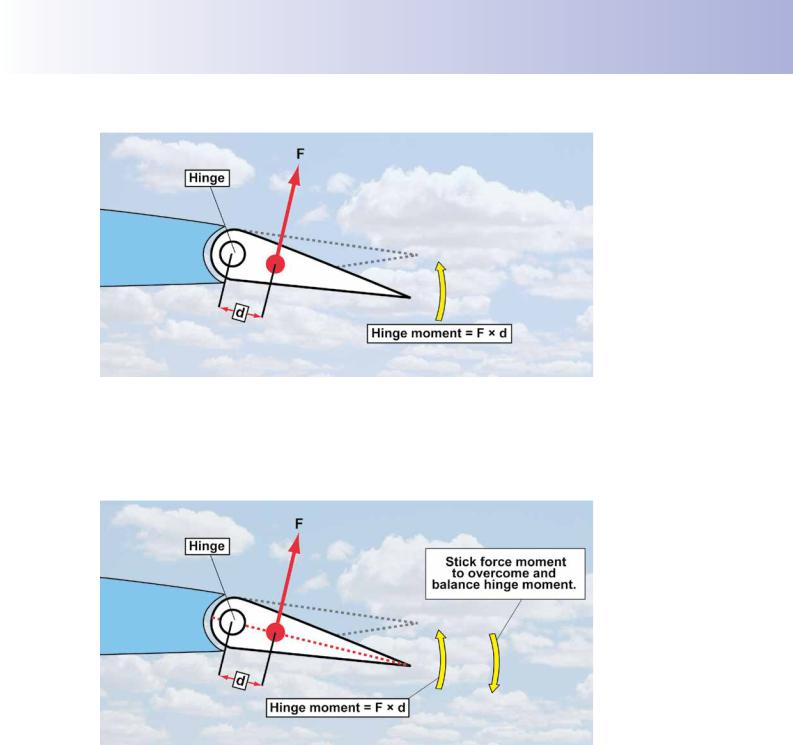
By the nature of the design of the control surface, the aerodynamic force, F, acting from the centre of pressure of the control surface will try to rotate the control surface about its hinge point, in the direction of the aerodynamic force, as depicted in Figure 12.20. This is called the hinge moment. Consequently, in order to move the fying control surface through the required angular displacement and maintain it in that position, the pilot has to overcome and then balance the hinge moment by applying a force to the control column or rudder pedals. This is called ‘stick force’. If the hinge moment increases the stick force applied by the pilot will also need to increase.
268
ID: 3658
Customer: Oleg Ostapenko E-mail: ostapenko2002@yahoo.com
Customer: Oleg Ostapenko E-mail: ostapenko2002@yahoo.com
CHAPTER 12: FLIGHT CONTROLS AND TRIMMING
Figure 12.20 The hinge moment at a control surface.
The relationship between stick force moment and hinge moment provides the pilot with feel or feedback information on the aerodynamic forces being generated at the control surfaces. At high speed, the stick force will be relatively high indicating to the pilot that, if he persists in trying to displace the fying controls to their full defection, structural damage may occur.
Figure 12.21 The control surface’s hinge moment must be balanced by a “stick force moment” applied by the pilot.
Balancing Stick Force.
Large jet transports like the Boeing 747 generate hinge moments of great magnitude which would be impossible for the pilot to overcome and balance without the assistance of powered controls and aerodynamic balancing. Powered assistance is usually provided by multiple engine-driven hydraulic systems.
269

Order: 6026
Customer: Oleg Ostapenko E-mail: ostapenko2002@yahoo.com
Customer: Oleg Ostapenko E-mail: ostapenko2002@yahoo.com
CHAPTER 12: FLIGHT CONTROLS AND TRIMMING
Figure 12.22 A Boeing 747.
However, light aircraft generally use simple mechanical linkages to operate the fying controls, with the pilot providing the force to operate them (See Figure 12.23).
Aerodynamic balancing does not reduce control effectiveness.
Figure 12.23 A mechanical elevator system in a light aircraft.
AERODYNAMIC BALANCING.
Although the forces required from the pilot to move the controls of a light aircraft are generally small in normal circumstances, the effort to move the controls at higher speeds, during continuous manoeuvring or in turbulence should not require high stick forces. For this reason, fying control surfaces are often balanced aerodynamically. Aerodynamic balancing is the most common and simplest form of balance on light aircraft. Aerodynamic balancing involves using the aerodynamic forces generated by the control surface itself, and can be achieved without reducing control effectiveness.
The Inset Hinge.
One method of aerodynamic balancing is the inset hinge. Figure 12.20 on Page 269 represents the normal hinge located near to the leading edge of the control, creating a large hinge moment. In Figure 12.24, however, the control surface hinge has been moved aft closer to the centre of pressure of the control surface so that the hinge moment is reduced. In addition, the airfow strikes the control surface in front of the hinge at F1, providing a turning moment which further reduces the hinge moment. This arrangement helps the pilot to move the controls by reducing the required stick force.
270

ID: 3658
Customer: Oleg Ostapenko E-mail: ostapenko2002@yahoo.com
Customer: Oleg Ostapenko E-mail: ostapenko2002@yahoo.com
CHAPTER 12: FLIGHT CONTROLS AND TRIMMING
Figure 12.24 The inset hinge, produces a smaller hinge moment than the normal hinge.
The Horn Balance.
Similar in operation to the inset hinge is the horn balance, shown in Figure 12.25.
The horn is the part of the fying control surface located forward of the hinge. In fight, when the control surface is displaced, aerodynamic forces will be generated both forward and aft of the hinge line. The moment generated by the aerodynamic force forward of the hinge counters the main control surface hinge moment, and assists the pilot to move the control surface. A disadvantage of the horn balance is that it produces an increase in overall drag, but conversely the horn itself facilitates provision of mass balancing (see page 274-5).
Figure 12.25 A horn balance system on a Zlin 242L.
In
aerodynamic balancing,
there is an
area of control surface forward of the hinge.
The Internal Balance.
The same principle as the horn balance is employed, without leading to an increase in drag, in the internal balance. The internal balance mechanism is enclosed inside the rear of the main aerofoil section, as depicted in Figure 12.26. The internal balance takes the form of a chamber which senses the same changes in pressure as those produced by the defection of the control surface, itself. The pressure differential inside the chamber produces moment in opposition to the hinge moment.
271

Order: 6026
Customer: Oleg Ostapenko E-mail: ostapenko2002@yahoo.com
Customer: Oleg Ostapenko E-mail: ostapenko2002@yahoo.com
CHAPTER 12: FLIGHT CONTROLS AND TRIMMING
Neither the internal hinge, the horn balance nor the internal balance has any adverse effect upon the principal aerodynamic force produced at the control surface.
Figure 12.26 The Internal Balance.
TRAILING-EDGE TABS.
The stick force required from the pilot to move the fying control surfaces can also be reduced by small aerofoil tabs, known as trailing-edge tabs, positioned at the rear of the control surface. Trailing-edge tabs do, however, alter the effectiveness of the fying control concerned.
There are three main types of trailing-edge tab device. They are:
•the balance tab.
•the anti-balance tab.
•the servo tab.
These tabs are small aerofoil sections, hinged at the trailing-edge of the fying control surfaces (See Figure 12.27).
Figure 12.27 Trailing edge tabs, in this case a balance tab.
The other tab is the elevator trim tab.
272

ID: 3658
Customer: Oleg Ostapenko E-mail: ostapenko2002@yahoo.com
Customer: Oleg Ostapenko E-mail: ostapenko2002@yahoo.com
CHAPTER 12: FLIGHT CONTROLS AND TRIMMING
The Balance Tab.
The balance tab aids the pilot in moving the control surface. With the balance tab system, the pilot has no direct control over tab movement. Elevator movement is transmitted via a linkage which moves the balance tab in the opposite direction to the fying control surface, as depicted in Figure 12.28 ,and just visible in Figure 12.27.
Figure 12.28 A balance tab. The balance tab aids the pilot in moving the control surface.
The pilot moves the control surface through a control rod and, in turn, the control surface movement actuates the balance tab movement. The balance tab generates a force in the opposite direction to that generated by the main fying control surface.
The balance tab force reduces the control surface hinge moment and, thereby, the stick force required from the pilot. The balance tab does, however, cause a slight reduction in control effectiveness.
The Anti-Balance Tab.
Anti-balance tabs increase the stick force required from the pilot in order to provide him with “feel”. Aircraft ftted with all-fying tailplanes are capable of producing very signifcant aerodynamic forces as a result of their large surface area and their principle of operation. The danger exists, therefore, especially at high speed, that the pilot may over-control and consequently over-stress the aircraft. It is, therefore, desirable to increase the stick force and provide the pilot with “feel”. This objective is achieved by the anti-balance tab. (See Figure 12.29.) The anti-balance tab operates in the same direction as the fying control surface and thus increases the stick force required to displace the control surface. This arrangement increases the effectiveness of the control surface itself. You may also hear the American term ‘anti-servo tab’ applied to this type of tab.
Balance tabs
move in the opposite
direction to
the control surface to assist the pilot in moving the control surface.
Anti-Balance
tabs move in the same
direction as
the control surface to increase stick force in order to provide the pilot with “feel”.
Figure 12.29 The anti-balance tab moves in the same direction as the control surface to increase stick force and provide the pilot with “feel”.
273

Order: 6026
Customer: Oleg Ostapenko E-mail: ostapenko2002@yahoo.com
Customer: Oleg Ostapenko E-mail: ostapenko2002@yahoo.com
CHAPTER 12: FLIGHT CONTROLS AND TRIMMING
A servo tab is a pilot-
controlled tab which causes
the flying control surface to move.
Figure 12.30 Anti-balance tabs are most commonly found on aircraft with all-flying tailplanes or stabilators.
The Servo Tab.
The mechanism of the servo tab differs from the other types of tabs in that the pilot’s control input is to the servo tab and not to the fying control surface. Movement of the servo tab creates an aerodynamic force which moves the main fying control surface.
For instance, if the pilot selects a nose-up pitch attitude, his input to the control column moves the servo tab downwards which, in turn, generates an aerodynamic force which displaces the main fying control upwards.
Figure 12.31 The servo tab provides the force which displaces the flying control surface.
MASS BALANCING.
Flutter.
There is one method of balancing which is applied to fying control surfaces but which has nothing to do with alleviating stick force. This is called mass balancing. Mass balancing is used to prevent control surface futter, a phenomenon which is often associated with high aircraft speeds. Flutter is the name given to the oscillation of a fying control surface at high speed, and can cause bending or twisting of the surface.
Flutter can occur as a result of the centre of gravity (C of G) of the control surface being well aft of the hinge.
274

ID: 3658
Customer: Oleg Ostapenko E-mail: ostapenko2002@yahoo.com
Customer: Oleg Ostapenko E-mail: ostapenko2002@yahoo.com
CHAPTER 12: FLIGHT CONTROLS AND TRIMMING
A detailed examination of futter is beyond the scope of this book. Here it is suffcient for us to state that if futter arises and the oscillations remain undamped, structural failure of the control surface can occur.
Figure 12.32 Flutter can arise if the centre of gravity of the control surface is well aft of the hinge.
Flutter in a
control surface reduced by
fixing a mass
forward of the hinge to move the C of G of the control surface closer to the hinge.
Figure 12.33 Mass balancing moves the C of G position nearer to the hinge and prevents flutter.
Flutter can be prevented by modifying the distribution of the mass of the control surface so that the C of G of the control surface lies nearer to the hinge (See Figures 12.32, 12.33). It is because of this method of redistribution of mass that this device is called mass-balancing. Figure 12.34 illustrates aileron mass balancing on the Zlin
242L. See also Figure 12.27 for elevator mass balance.
Figure 12.34 The mass balance fitted to the ailerons of a Zlin 242L.
275

Order: 6026
Customer: Oleg Ostapenko E-mail: ostapenko2002@yahoo.com
Customer: Oleg Ostapenko E-mail: ostapenko2002@yahoo.com
CHAPTER 12: FLIGHT CONTROLS AND TRIMMING
A fixed trim tab will trim the aircraft for one airspeed only.
TRIMMING.
Introduction.
An aircraft is said to be trimmed, or in trim, when it is able to maintain its selected attitude without the pilot applying any force to the control column.
When an aircraft is in trim, the stick force is zero. Flying in trim, therefore, means that the pilot is less susceptible to fatigue and is also free to attend to other required tasks, such as navigation.
Your very frst fying lesson will have made you aware of the varying magnitude of the force that you have to apply to the control wheel and rudder pedals in order to select and maintain an attitude, other than the attitude for which the aircraft is trimmed. The design of an aircraft is such that, in still air, at a given airspeed, power setting and confguration, the aircraft will be trimmed to one attitude only. If the pilot changes power-setting or aircraft confguration (by selecting fap, for instance), or selects and maintains any other attitude, he has, once again, to apply a force to the controls to hold the attitude.
But by using the aircraft’s trimming control system the pilot can trim out the need to apply a force to the control wheel to maintain the new attitude.
Most simple light aircraft can be trimmed in fight to remove stick force in the pitching plane only (elevator trim), though directional trim (rudder trim) is ftted to some light aircraft.
The three most common methods of trimming a light aircraft are:
•The fxed trim tab.
•The adjustable trim tab.
•Spring-bias trimming.
Fixed Trim Tabs.
The most basic method of achieving trimmed fight is with a fxed trim tab. The fxed trim tab is a narrow metal plate attached to the trailing edge of a control surface, usually the aileron (See Figure 12.35).
Figure 12.35 A fixed trim tab on a aileron.
276