

ppl_05_e2
.pdfID: 3658
Customer: Oleg Ostapenko E-mail: ostapenko2002@yahoo.com
Customer: Oleg Ostapenko E-mail: ostapenko2002@yahoo.com
CHAPTER 10: LIFT AUGMENTATION
Figure 10.12 The Fowler fap.
COMPARISON OF CL AND CLMAX FOR DIFFERENT TYPES OF
FLAP.
A comparison of the coeffcient of lift, CL, and the coeffcient of drag, CD, for a basic wing section and for a wing with different types of fap deployed, at the same angle of attack, is shown graphically in the right hand graph in Figure 10.13.
Compared to the basic wing section, it can be seen that all types of fap increase
CL and CD, at a given angle of attack. Note that the Fowler Flap almost doubles CL, compared to the basic wing section, for a modest increase in drag.
Figure 10.13 Comparison of CL and CD for different types of flap.
The Effect of Flap on Stalling Angle of Attack.
Take particular note from the left hand graph in Figure 10.13 of what happens to the stalling angle of attack for the overall wing when faps are extended, remembering
that CLMAX is reached just before the stall. You see that, with faps extended, the stall occurs at a lower angle of attack than for the basic wing section: the so-called
“clean wing”.
Extending flaps reduces the stalling angle of attack.
207
Order: 6026
Customer: Oleg Ostapenko E-mail: ostapenko2002@yahoo.com
Customer: Oleg Ostapenko E-mail: ostapenko2002@yahoo.com
CHAPTER 10: LIFT AUGMENTATION
With flaps lowered,
stalling speed will decrease and stalling angle of attack will
be reduced.
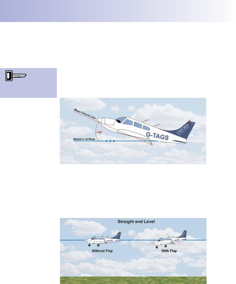
Imagine that an aircraft is fying close to the stall with its wing at just below the stalling angle of attack. If fap is now lowered, the mean chord line of the wing will be displaced and the stalling angle of attack will be exceeded. So, to prevent the stall occurring, the angle of attack between the relative airfow and the mean chord line must be reduced, by the pilot selecting a lower nose attitude.
Lowering faps reduces the stalling angle of attack of the wing by about 2-3 degrees. As a consequence, when carrying out a stalling exercise from straight and level fight, with faps extended, the pilot will notice that the aircraft stalls at a lower nose attitude than with the wing clean, although, this lower attitude is likely to be also due to the effect noted below, despite the lower fap-down stalling speed (which is covered later).
Figure 10.14 When flaps are lowered, the change in the mean chord line changes the angle of attack.
FLAP EXTENSION - EFFECT ON PITCH CHANGE AND NOSE ATTITUDE.
Whatever phase of fight the aircraft is in, whether climbing, descending or in straight and level fight, at a given speed the aircraft will always have a more pronounced nose-down attitude with faps extended than with faps retracted. Figure 10.15 depicts an aircraft in straight and level fight with and without faps extended.
Figure 10.15 At any given speed, an aircraft with flaps extended has a more pronounced nose-down attitude than with flaps raised.
208
ID: 3658
Customer: Oleg Ostapenko E-mail: ostapenko2002@yahoo.com
Customer: Oleg Ostapenko E-mail: ostapenko2002@yahoo.com
CHAPTER 10: LIFT AUGMENTATION
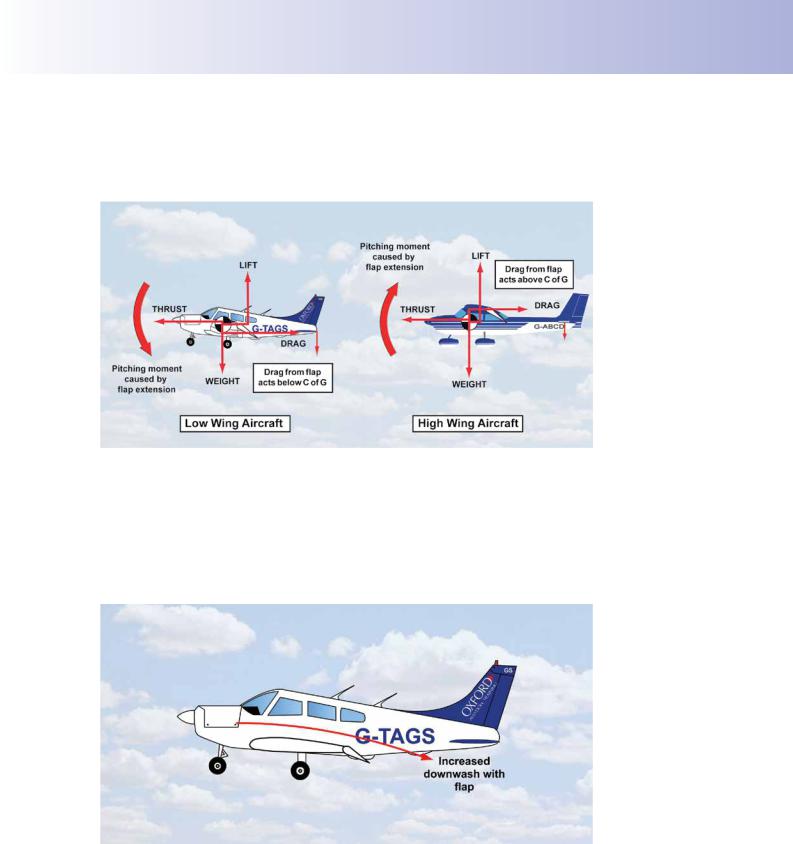
It is possible that the aircraft may pitch down of its own accord when the pilot extends faps. This depends on the aircraft type. But whether or not an aircraft initially pitches up or down on faps selection will often depend on whether the aircraft is of a high, low or mid wing design (see Figure 10.16).
Figure 10.16 The thrust-drag couple either opposes or assists the pitching moment, depending upon the position of the wing.
The modifcation of downwash in the airfow, when fap is selected, will also affect an aircraft’s reaction, in the pitching plane, to fap selection. Downwash is increased with faps extended because the airfow will tend to follow the increased camber of the wing’s upper surface (See Figure 10.17). The extent to which the increased downwash affects the aircraft in the pitching plane will be determined by whether the tailplane or stabilator is high or low-mounted.
Figure 10.17 Lowering flap will modify downwash and influence an aircraft’s trim in the pitching plane.
To sum up, then, the effect of fap selection on an aircraft’s longitudinal trim will differ between aircraft types, depending on the location of the main wing, the position of the tailplane, and the position of the line of action of propeller thrust. All these factors will determine the eventual pitch attitude change of the aircraft when the pilot selects trailing edge faps.
209
Order: 6026
Customer: Oleg Ostapenko E-mail: ostapenko2002@yahoo.com
Customer: Oleg Ostapenko E-mail: ostapenko2002@yahoo.com
CHAPTER 10: LIFT AUGMENTATION
Lowering flap will always
reduce the lift/ drag ratio, so
glide angle will be steeper and climb angle will be shallower.
Note that the PA28 Warrior, if trimmed in pitch for steady fight, will pitch up when the faps are lowered.
Maximum Lift-Drag Ratio.
As we saw in Figure 10.13, the selection of faps increases both lift and drag, but not in the same proportion. The proportional increase in drag is always greater, which means that, with faps deployed, the maximum lift/drag ratio is always reduced, as depicted in Figure 10.18.
As you have learnt, the lift-drag ratio is a measure of a wing’s aerodynamic effciency, and so, when faps are lowered, the aircraft’s maximum climb angle, best glide performance and maximum range are all reduced. The greater the angle of fap setting used, the greater will be the reduction in these aspects of aircraft performance.
Figure 10.18 Selecting flap always reduces the lift/drag ratio.
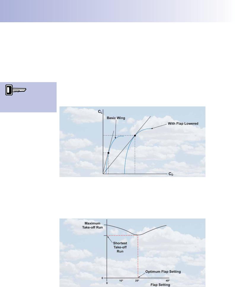
Take-Off Flap.
For take-off, increasing CL to its maximum value by selecting a large amount of fap would give the lowest minimum fight speed, but drag would also be at its maximum, which could reduce acceleration to such an extent that the take-off run would be unacceptably long. Consequently, a smaller fap setting than full fap is usually used for take-off. The Pilot’s Operating Handbook will state the optimum fap setting to be used.
Figure 10.19 Optimum Flap Setting for Take-off.
210
ID: 3658
Customer: Oleg Ostapenko E-mail: ostapenko2002@yahoo.com
Customer: Oleg Ostapenko E-mail: ostapenko2002@yahoo.com
CHAPTER 10: LIFT AUGMENTATION
Figure 10.19 illustrates that, for a representative aircraft, the shortest take-off distance occurs with 25º of fap selected. The take-off distance increases if a lower or greater fap setting is used.
Flap Retraction after Take-Off.
After take-off the faps are retracted to improve the climb angle. However, great care must be exercised when raising fap. Because of the changes in CL, drag and pitching moments which occur on fap retraction, the faps should be raised in stages.
Furthermore, to prevent any sudden loss of lift as the faps are retracted, the aircraft must frst be accelerated to a safe speed, but not beyond VFE (see overleaf).
The important consideration at this stage of fight is that the aircraft should not be allowed to sink, especially when it is close to the ground.
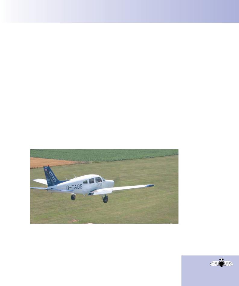
Landing Flap.
When landing, the high drag associated with the use of higher fap settings is a beneft to the aircraft. The less favourable lift - drag ratio also enables a suitably steep glide path to be fown for the approach, and, after touch-down, the extra drag will help reduce the distance of the landing run. The higher values of CL produced with faps lowered will enable the approach to be fown at the lowest possible speeds.
Figure 10.20 Deployment of landing flap.
The approach speed must remain, however, at least 1.3 times the stalling speed.
During the approach, the faps are lowered in stages to reduce the effects of the changes in lift, drag and pitch attitude on the aircraft.
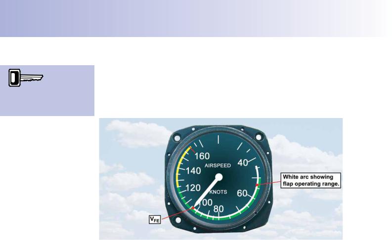
Since lift is proportional to the square of the airspeed, as well as directly proportional to CL, it follows that if faps are selected at too high an airspeed, the large lift force produced could overstress the airframe or fap-operating mechanism. To ensure that neither is overstressed, faps should not be selected until the aircraft has slowed down to a defned airspeed. This speed is known as VFE which signifes “Velocity
Flaps Extended”.
Flap should not be selected until
the airspeed is within the defined operating range (white arc).
211
Order: 6026
Customer: Oleg Ostapenko E-mail: ostapenko2002@yahoo.com
Customer: Oleg Ostapenko E-mail: ostapenko2002@yahoo.com
CHAPTER 10: LIFT AUGMENTATION
The maximum speed at
which the aircraft can
be flown with flaps extended is VFE, at the top of the white arc.
The faps-extended speed-range is marked on the Airspeed Indicator by a white arc, as shown in Figure 10.21. The faps can be safely operated if the aircraft’s speed is within this arc. VFE is the airspeed reading at the higher end of the white arc. In Figure 10.21, VFE is 104 knots. Bear in mind that not only must the faps not be lowered until the airspeed has reduced below VFE, but faps must also be fully retracted before the aircraft accelerates above VFE.
Figure 10.21 The flaps can safely be operated if the aircraft’s speed is within the white arc.
Flap Selection for Approach and Landing.
On the approach to land, the pilot gradually slows the aircraft down, progressively selecting more stages of fap. Remember that, when selecting faps, it is necessary to pitch the nose of the aircraft down in order to maintain the value of CL constant by reducing the angle of attack. This action will also improve the pilot’s view of the airfeld and the runway.
Full landing fap is selected only when the pilot is confdent of achieving the runway aiming point and intends to land.
LEADING EDGE HIGH-LIFT DEVICES.
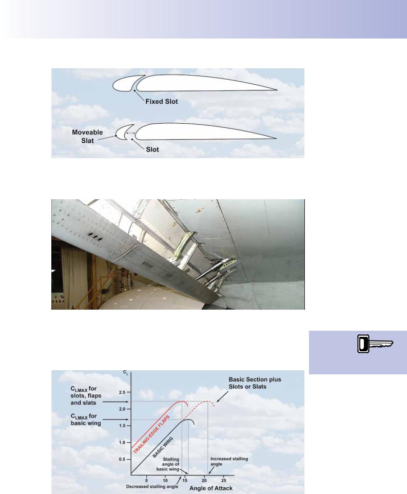
There are two types of leading edge high-lift device. These are the slot and slat illustrated in Figure 10.22, and the leading edge fap shown in Figure 10.23.
You should note that the term slot is applied to the gap which connects the undersurface and upper-surface of the wing’s leading edge. The slot can either be fxed, as in the higher of two drawings in Figure 10.22, or it can open or close depending on the position of a moveable auxiliary aerofoil known as a slat, depicted in the lower drawing at Figure 10.22.
212
ID: 3658
Customer: Oleg Ostapenko E-mail: ostapenko2002@yahoo.com
Customer: Oleg Ostapenko E-mail: ostapenko2002@yahoo.com
CHAPTER 10: LIFT AUGMENTATION
Figure 10.22 The slot and the slat.
Leading edge faps are a complex mechanical fap system, used only on large jet transport aircraft. (See Figure 10.23). Those few light aircraft with leading edge high lift devices are more likely to use slots or slats.
Figure 10.23 A typical leading edge flap on a jet transport aircraft.
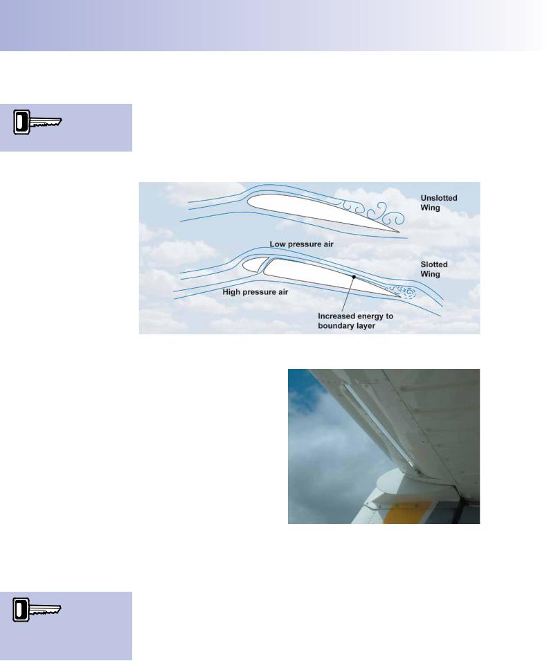
The main purpose of leading edge devices is to increase CLMAX. Slots/slats achieve this by delaying separation by re-energising the boundary layer; this increases the
stalling angle of attack. Leading edge faps achieve the rise in CLMAX by increase increasing the camber and/or surface area of the wing and actually reduce the stalling
AoA.
Leading
edge devices
increase CLMAX and modify the
stalling angle of attack.
Figure 10.24 Leading edge devices increase the stalling angle of attack whereas trailing edge flaps reduce it.
213
Order: 6026
Customer: Oleg Ostapenko E-mail: ostapenko2002@yahoo.com
Customer: Oleg Ostapenko E-mail: ostapenko2002@yahoo.com
CHAPTER 10: LIFT AUGMENTATION
Trailing edge flaps reduce the stalling angle
The Leading Edge Slot.
The leading edge slot is a fxed gap between the lower surface and the upper surface of the wing leading edge, stretching from near the wing root to just short of the wing tip.
The leading edge slot re-directs high pressure air from below the wing, through the slot, in order to re-energise the boundary layer and so delay separation. See Figure 10.25.
Figure 10.25 The leading edge slot redirects high pressure air from the undersurface of the wing to the upper surface of the wing.
The tailplane is also an aerofoil and may be ftted with slots See Figure 10.26, but inverted, as the tailplane’s purpose is to produce downforce. The illustration is of the stabilator on a PA28 Arrow 4 (T-tail), where the slot maintains effciency with high ‘nose up’ demands.
Figure 10.26 The tailplane is an aerofoil and may be fitted with slots.
The wing’s Centre of
Pressure moves
forward as the angle of attack increases.
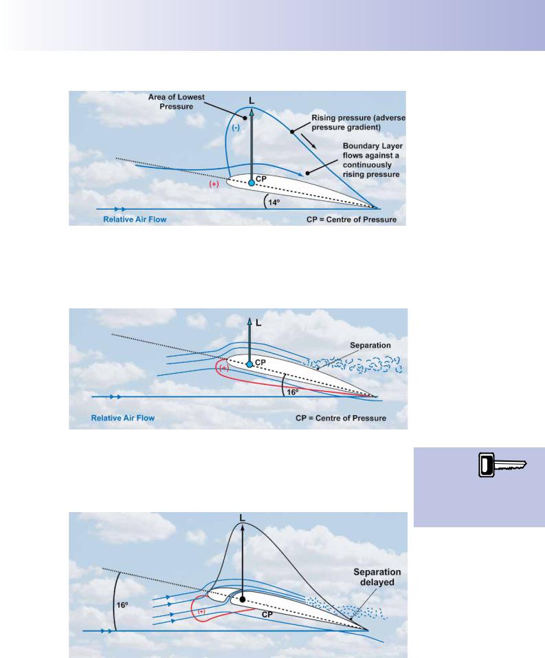
The Principle of Operation of the Leading-Edge Slot.
Consider an un-slotted wing whose angle of attack is increasing towards the stalling angle, as shown in Figure 10.27. As the angle of attack increases, the area of lowest pressure on the upper surface of the wing moves forward, and the rate of pressure increase towards the wing’s trailing edge increases. Consequently, the boundarylayer is fowing against a continually rising pressure, or steepening adverse pressure gradient. (Note that the greater the vertical extent of the pressure distribution envelope on the wing’s upper surface, the lower the static pressure).
214
ID: 3658
Customer: Oleg Ostapenko E-mail: ostapenko2002@yahoo.com
Customer: Oleg Ostapenko E-mail: ostapenko2002@yahoo.com
CHAPTER 10: LIFT AUGMENTATION
Figure 10.27 At 14º angle of attack the area of lowest pressure has moved well forward.
The further forward the point of lowest pressure the steeper the adverse pressure gradient becomes. The airfow in the boundary layer fnds it harder and harder to fow against this rising pressure and starts to separate from the upper surface. At the point of stall, the large adverse pressure gradient has caused the point of separation to move so far forward that there is a marked loss of lift. (See Figure 10.28).
Figure 10.28 At 16º, the stalling angle of attack, the pressure gradient causes the airflow over the upper surface to separate.
But with the slotted wing, as depicted in Figure 10.29, the slot enables the airfow to |
By re- |
|||
energising the |
|
|
||
continue against the adverse pressure gradient, at higher angles of attack, without |
|
|
||
|
||||
boundary layer, |
||||
separating, by increasing the energy of the boundary layer. The re-energising of |
||||
the slot delays |
||||
the boundary layer delays separation and increases the angle of attack at which the |
||||
separation and causes the |
||||
wing stalls. |
wing to stall at a higher angle |
|||
|
of attack. |
|||
Figure 10.29 The slot re-energises the boundary layer delaying separation and increasing the stalling angle of attack.
215
Order: 6026
Customer: Oleg Ostapenko E-mail: ostapenko2002@yahoo.com
Customer: Oleg Ostapenko E-mail: ostapenko2002@yahoo.com
CHAPTER 10: LIFT AUGMENTATION
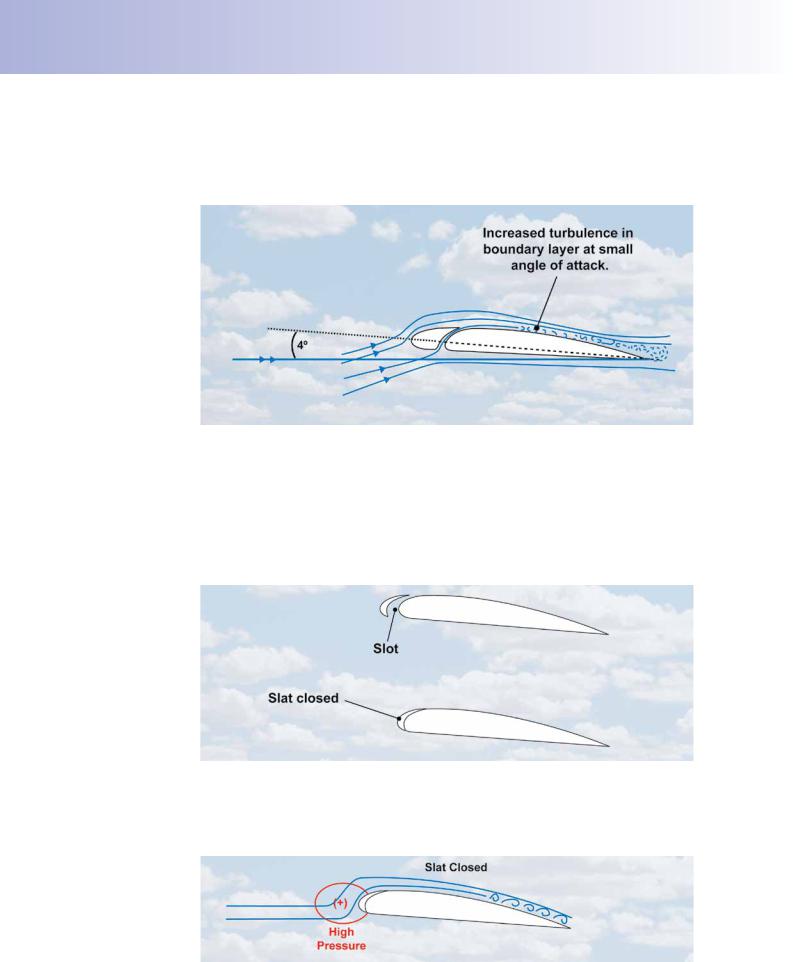
The slot, of course, will also direct higher pressure air to the upper surface of the wing even at low angles of attack. In this situation, the re-energised airfow thickens the boundary layer causing it to become turbulent (See Figure 10.30). This phenomenon increases drag which is not desirable at cruising speed.
Figure 10.30 At low angles of attack the fixed slot thickens the boundary layer, increasing drag.
The drag problem of the fxed slot can, however, be overcome by making the slot adjustable. This aim is achieved by ftting slats.
The Leading-Edge Slat.
A slat is a small moveable aerofoil section attached to the leading edge of the wing. When the slat deploys by moving away from the leading edge, it forms a slot, as depicted in Figure 10.31.
Figure 10.31 Operation of the slat creates an opening which forms a slot.
The slat normally operates automatically in response to varying airfow pressures at the leading edge of the wing. At small angles of attack the high pressure at the leading edge holds the slat closed, as shown in Figure 10.32.
Figure 10.32 High pressure at the leading edge keeps the slat closed at small angles of attack.
216