
Министерство образования и науки Российской Федерации
Федеральное государственное бюджетное образовательное учреждение
высшего профессионального образования
«ВОЛГОГРАДСКИЙ ГОСУДАРСТВЕННЫЙ ТЕХНИЧЕСКИЙ УНИВЕРСИТЕТ»
(ВолгГТУ)
Кафедра иностранных языков
Семестровая работа за I семестр
по английскому языку
Тема:«DMA controller (DMA)»
Источник: WWW.EDUCATION.RU
Выполнил: студент группы УТС-1 Николаев Е. В.
Проверила:
Багметова Н. В.
Краткая рецензия: As the initial text was selected “Reference manual” for a family of microcontrollers STM32F4XX. Original text of this manual can be viewed at the link http://www.st.com/web/en/resource/technical/document/reference_manual/DM00031020.pdf. It should be noted that the text of this link may differ from the text used in the work because of documentation updates. Of this manual has been selected a section on Direct Memory Access.
Оценка работы _________________ баллов
Волгоград, 2015 содержание
1 ИСХОДНЫЙ ТЕКСТ 3
2 ПЕРЕВОД 16
3 СЛОВАРЬ 30
4 ПЕРЕСКАЗ 33
1 Исходный текст
DMA controller (DMA)
This section applies to the whole STM32F4xx family, unless otherwise specified.
1 DMA introduction
Direct memory access (DMA) is used in order to provide high-speed data transfer between peripherals and memory and between memory and memory. Data can be quickly moved by DMA without any CPU action. This keeps CPU resources free for other operations.
The DMA controller combines a powerful dual AHB master bus architecture with independent FIFO to optimize the bandwidth of the system, based on a complex bus matrix architecture.
The two DMA controllers have 16 streams in total (8 for each controller), each dedicated to managing memory access requests from one or more peripherals. Each stream can have up to 8 channels (requests) in total. And each has an arbiter for handling the priority between DMA requests.
2 DMA main features
The main DMA features are:
• Dual AHB master bus architecture, one dedicated to memory accesses and one dedicated to peripheral accesses
• AHB slave programming interface supporting only 32-bit accesses
• 8 streams for each DMA controller, up to 8 channels (requests) per stream
• Four separate 32 first-in, first-out memory buffers (FIFOs) per stream, that can be used in FIFO mode or direct mode:
– FIFO mode: with threshold level software selectable between 1/4, 1/2 or 3/4 of the FIFO size
– Direct mode
Each DMA request immediately initiates a transfer from/to the memory. When it is configured in direct mode (FIFO disabled), to transfer data in memory-to-peripheral mode, the DMA preloads only one data from the memory to the internal FIFO to ensure an immediate data transfer as soon as a DMA request is triggered by a peripheral.
• Each stream can be configured by hardware to be:
– a regular channel that supports peripheral-to-memory, memory-to-peripheral and memory-to-memory transfers
– a double buffer channel that also supports double buffering on the memory side Each of the 8 streams are connected to dedicated hardware DMA channels (requests)
• Priorities between DMA stream requests are software-programmable (4 levels consisting of very high, high, medium, low) or hardware in case of equality (request 0 has priority over request 1, etc.)
• Each stream also supports software trigger for memory-to-memory transfers (only available for the DMA2 controller)
• Each stream request can be selected among up to 8 possible channel requests. This selection is software-configurable and allows several peripherals to initiate DMA requests
• The number of data items to be transferred can be managed either by the DMA controller or by the peripheral:
– DMA flow controller: the number of data items to be transferred is software-programmable from 1 to 65535
– Peripheral flow controller: the number of data items to be transferred is unknown and controlled by the source or the destination peripheral that signals the end of the transfer by hardware
• Independent source and destination transfer width (byte, half-word, word): when the data widths of the source and destination are not equal, the DMA automatically packs/unpacks the necessary transfers to optimize the bandwidth. This feature is only available in FIFO mode
• Incrementing or nonincrementing addressing for source and destination
• Supports incremental burst transfers of 4, 8 or 16 beats. The size of the burst is software-configurable, usually equal to half the FIFO size of the peripheral
• Each stream supports circular buffer management
• 5 event flags (DMA Half Transfer, DMA Transfer complete, DMA Transfer Error, DMA FIFO Error, Direct Mode Error) logically ORed together in a single interrupt request for each stream
3 DMA functional description
3.1 General description
Figure 32 shows the block diagram of a DMA.
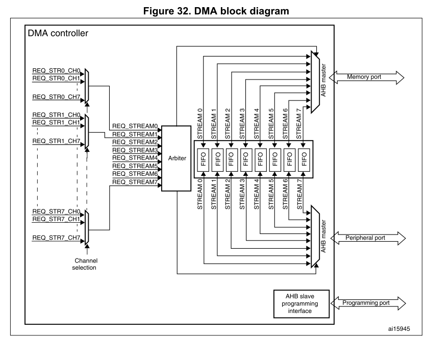
The DMA controller performs direct memory transfer: as an AHB master, it can take the control of the AHB bus matrix to initiate AHB transactions.
It can carry out the following transactions:
• peripheral-to-memory
• memory-to-peripheral
• memory-to-memory
The DMA controller provides two AHB master ports: the AHB memory port, intended to be connected to memories and the AHB peripheral port, intended to be connected to peripherals. However, to allow memory-to-memory transfers, the AHB peripheral port must also have access to the memories.
The AHB slave port is used to program the DMA controller (it supports only 32-bit accesses).
See Figure 33 and Figure 34 for the implementation of the system of two DMA controllers.
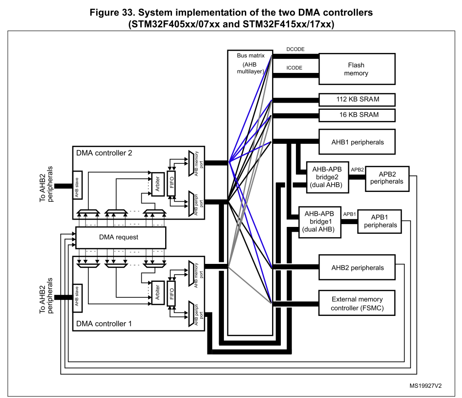
1. The DMA1 controller AHB peripheral port is not connected to the bus matrix like in the case of the DMA2 controller, thus only DMA2 streams are able to perform memory-to-memory transfers.
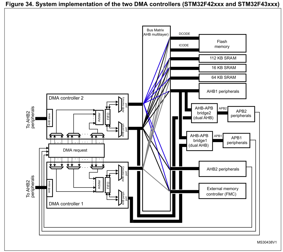
1. The DMA1 controller AHB peripheral port is not connected to the bus matrix like in the case of the DMA2 controller, thus only DMA2 streams are able to perform memory-to-memory transfers.
3.2 DMA transactions
A DMA transaction consists of a sequence of a given number of data transfers. The number of data items to be transferred and their width (8-bit, 16-bit or 32-bit) are software-programmable.
Each DMA transfer consists of three operations:
• A loading from the peripheral data register or a location in memory, addressed through the DMA_SxPAR or DMA_SxM0AR register
• A storage of the data loaded to the peripheral data register or a location in memory addressed through the DMA_SxPAR or DMA_SxM0AR register
• A post-decrement of the DMA_SxNDTR register, which contains the number of transactions that still have to be performed
After an event, the peripheral sends a request signal to the DMA controller. The DMA controller serves the request depending on the channel priorities. As soon as the DMA controller accesses the peripheral, an Acknowledge signal is sent to the peripheral by the DMA controller. The peripheral releases its request as soon as it gets the Acknowledge signal from the DMA controller. Once the request has been deasserted by the peripheral, the DMA controller releases the Acknowledge signal. If there are more requests, the peripheral can initiate the next transaction.
3.3 Channel selection
Each stream is associated with a DMA request that can be selected out of 8 possible channel requests. The selection is controlled by the CHSEL[2:0] bits in the DMA_SxCR register.
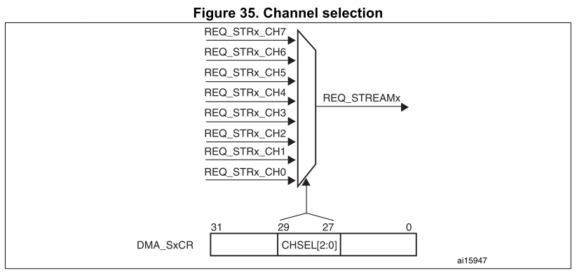
The 8 requests from the peripherals (TIM, ADC, SPI, I2C, etc.) are independently connected to each channel and their connection depends on the product implementation.
Table 43 and Table 44 give examples of DMA request mappings.
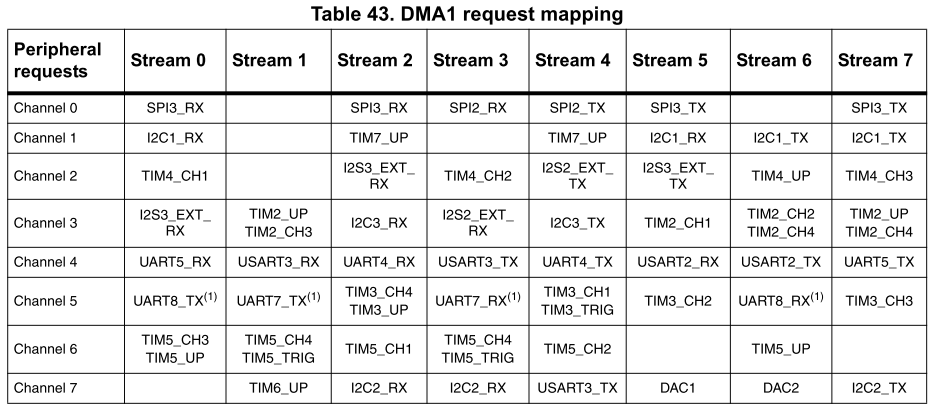
1. These requests are available on STM32F42xxx and STM32F43xxx only.

1. These requests are available on STM32F42xxx and STM32F43xxx.
3.4 Arbiter
An arbiter manages the 8 DMA stream requests based on their priority for each of the two AHB master ports (memory and peripheral ports) and launches the peripheral/memory access sequences.
Priorities are managed in two stages:
• Software: each stream priority can be configured in the DMA_SxCR register. There are four levels:
– Very high priority
– High priority
– Medium priority
– Low priority
• Hardware: If two requests have the same software priority level, the stream with the lower number takes priority over the stream with the higher number. For example, Stream 2 takes priority over Stream 4.
3.5 DMA streams
Each of the 8 DMA controller streams provides a unidirectional transfer link between a source and a destination.
Each stream can be configured to perform:
• Regular type transactions: memory-to-peripherals, peripherals-to-memory or memory-to-memory transfers
• Double-buffer type transactions: double buffer transfers using two memory pointers for the memory (while the DMA is reading/writing from/to a buffer, the application can write/read to/from the other buffer).
The amount of data to be transferred (up to 65535) is programmable and related to the source width of the peripheral that requests the DMA transfer connected to the peripheral AHB port. The register that contains the amount of data items to be transferred is decremented after each transaction.
3.6 Source, destination and transfer modes
Both source and destination transfers can address peripherals and memories in the entire 4 GB area, at addresses comprised between 0x0000 0000 and 0xFFFF FFFF.
The direction is configured using the DIR[1:0] bits in the DMA_SxCR register and offers three possibilities: memory-to-peripheral, peripheral-to-memory or memory-to-memory transfers. Table 45 describes the corresponding source and destination addresses.

When the data width (programmed in the PSIZE or MSIZE bits in the DMA_SxCR register) is a half-word or a word, respectively, the peripheral or memory address written into the DMA_SxPAR or DMA_SxM0AR/M1AR registers has to be aligned on a word or half-word address boundary, respectively.
Peripheral-to-memory mode
Figure 36 describes this mode.
When this mode is enabled (by setting the bit EN in the DMA_SxCR register), each time a peripheral request occurs, the stream initiates a transfer from the source to fill the FIFO.
When the threshold level of the FIFO is reached, the contents of the FIFO are drained and stored into the destination.
The transfer stops once the DMA_SxNDTR register reaches zero, when the peripheral requests the end of transfers (in case of a peripheral flow controller) or when the EN bit in the DMA_SxCR register is cleared by software.
In direct mode (when the DMDIS value in the DMA_SxFCR register is ‘0’), the threshold level of the FIFO is not used: after each single data transfer from the peripheral to the FIFO, the corresponding data are immediately drained and stored into the destination.
The stream has access to the AHB source or destination port only if the arbitration of the corresponding stream is won. This arbitration is performed using the priority defined for each stream using the PL[1:0] bits in the DMA_SxCR register.

1. For double-buffer mode.
Memory-to-peripheral mode
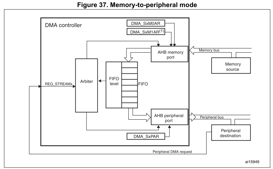
Figure 37 describes this mode.
When this mode is enabled (by setting the EN bit in the DMA_SxCR register), the stream immediately initiates transfers from the source to entirely fill the FIFO.
Each time a peripheral request occurs, the contents of the FIFO are drained and stored into the destination. When the level of the FIFO is lower than or equal to the predefined threshold level, the FIFO is fully reloaded with data from the memory.
The transfer stops once the DMA_SxNDTR register reaches zero, when the peripheral requests the end of transfers (in case of a peripheral flow controller) or when the EN bit in the DMA_SxCR register is cleared by software.
In direct mode (when the DMDIS value in the DMA_SxFCR register is '0'), the threshold level of the FIFO is not used. Once the stream is enabled, the DMA preloads the first data to transfer into an internal FIFO. As soon as the peripheral requests a data transfer, the DMA transfers the preloaded value into the configured destination. It then reloads again the empty internal FIFO with the next data to be transfer. The preloaded data size corresponds to the value of the PSIZE bitfield in the DMA_SxCR register.
The stream has access to the AHB source or destination port only if the arbitration of the corresponding stream is won. This arbitration is performed using the priority defined for each stream using the PL[1:0] bits in the DMA_SxCR register.
1. For double-buffer mode.
Memory-to-memory mode
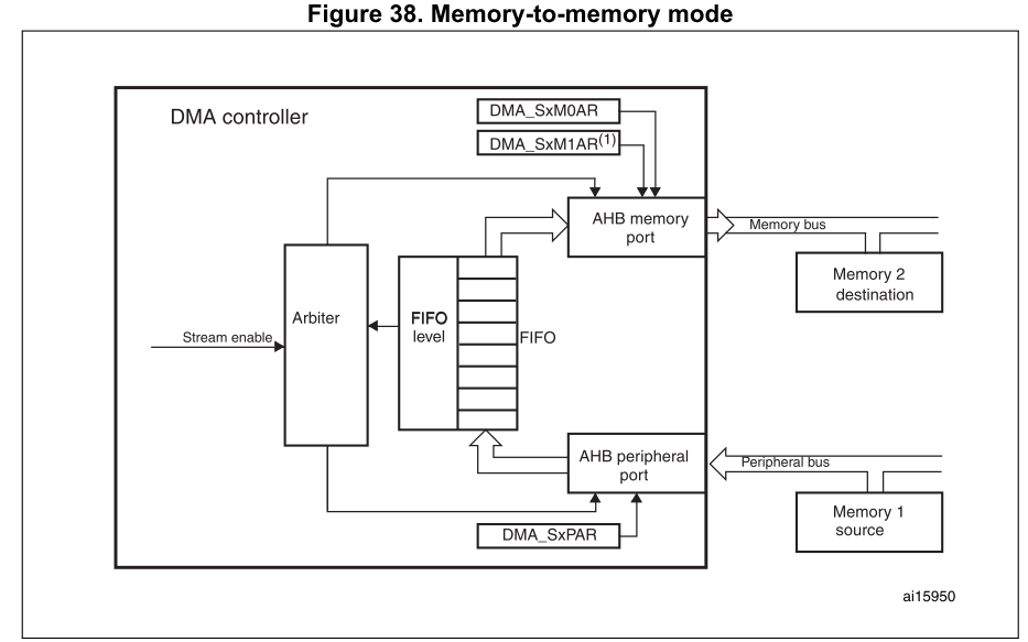
The DMA channels can also work without being triggered by a request from a peripheral. This is the memory-to-memory mode, described in Figure 38.
When the stream is enabled by setting the Enable bit (EN) in the DMA_SxCR register, the stream immediately starts to fill the FIFO up to the threshold level. When the threshold level is reached, the FIFO contents are drained and stored into the destination.
The transfer stops once the DMA_SxNDTR register reaches zero or when the EN bit in the DMA_SxCR register is cleared by software.
The stream has access to the AHB source or destination port only if the arbitration of the corresponding stream is won. This arbitration is performed using the priority defined for each stream using the PL[1:0] bits in the DMA_SxCR register.
Note: When memory-to-memory mode is used, the Circular and direct modes are not allowed.
Only the DMA2 controller is able to perform memory-to-memory transfers.
1. For double-buffer mode.
3.7 Pointer incrementation
Peripheral and memory pointers can optionally be automatically post-incremented or kept constant after each transfer depending on the PINC and MINC bits in the DMA_SxCR register.
Disabling the Increment mode is useful when the peripheral source or destination data are accessed through a single register.
If the Increment mode is enabled, the address of the next transfer will be the address of the previous one incremented by 1 (for bytes), 2 (for half-words) or 4 (for words) depending on the data width programmed in the PSIZE or MSIZE bits in the DMA_SxCR register.
In order to optimize the packing operation, it is possible to fix the increment offset size for the peripheral address whatever the size of the data transferred on the AHB peripheral port.
The PINCOS bit in the DMA_SxCR register is used to align the increment offset size with the data size on the peripheral AHB port, or on a 32-bit address (the address is then incremented by 4). The PINCOS bit has an impact on the AHB peripheral port only.
If PINCOS bit is set, the address of the next transfer is the address of the previous one incremented by 4 (automatically aligned on a 32-bit address) whatever the PSIZE value. The AHB memory port, however, is not impacted by this operation.
The PINC or the MINC bit needs to be set if the burst transaction is requested on the AHB peripheral port or the AHB memory port, respectively, to satisfy the AMBA protocol (burst is not allowed in the fixed address mode).
