

Учебники / Middle Ear Mechanics in Research and Otology Huber 2006
.pdfear systems are about as sensitive as any other. However, ossicular chains are usually able to work at higher frequencies than columella middle ear can do [1].
|
|
|
|
||
|
||
|
||
|
|
|
|
|
|
|
||
|
||
|
||
|
|
|
|
|
|
|
|
|
|
||
|
||
|
||
|
||
|
||
|
||
|
Fig. 1 Human ossicular chain and a schematically drawn “columella”.
Looking at Fig. 1 this fact is all the more surprising as the ossicular chain obviously contains more mass which should worsen the transmission of high frequencies because of inertial forces. The main mass is concentrated on both sides of the incudomalleal joint. One can assume that the comparably large masses of the malleus head and the incus body are necessary to implement a particularly robust joint in between. It is known that the
198incudomallealjointservesasanoverloadprotectorwhichreducesthee ect of external forces and static pressure on the inner ear. The role of the mass centre formed by the malleus head and the incus body has to be elucidated in the following.
The similar sensitivity of both systems in spite of di erent masses is explained by di erent kinds of vibration. At low frequencies the malleus and incus jointly rotate about the so called “main axis” which lies near the centre of gravity of both ossicles. This reduces the e ective mass. In contrast, the columella mainly vibrates translationally along the rod axis. On the other hand, at low frequencies inertial forces are small in any case. Thus a rotational vibration of the ossicles should be particularly expected at high frequencies.

2. Ossicular Vibrations for Acoustic Excitation
The vibrations of the ossicular chain were investigated using a “generalised circuitmodel”[2].Themodelisbasedonagreatvarietyoftransferfunctions measured by means of laser vibrometry. Simulations using a mathematical model have an invaluable advantage compared with experiments: conditions can be altered very easily and exactly to study the e ect of changes. In this short paper mostly normal conditions are considered.
|
|
|
|
|
|
|
|
|
|
||
|
|
|
|
|
|
|
|
|
|
|
|
|
|
|
|
|
|
|
|
|
|
|
|
|
|
|
|
|
|
|
|
|
|
|
|
|
|
||
|
|
|
|
|
|
|
|
|
|
|
|
|
|
|
199 |
|
|
||
|
|
|
|
|
|
|


Fig. 2 Vibrations of the ossicular chain for acoustic excitation at two frequencies. Trajectories provided at many points of the ossicles show the movement during one cycle of vibration. Equal grey tones in the trajectories correspond to equal points in time.

The patterns of vibration at di erent frequencies are best seen in animations, but also the representations in Fig. 2 can give an impression. At low frequencies the already mentioned rotation about the main axis is confirmed (not shown). At medium frequencies above 700–800 Hz we observe rocking motions. At high frequencies above 3–4 kHz particularly the manubrium vibrates very vigorously. At very high frequencies above 10 kHz even the short process of the incus begins to vibrate strongly (Fig. 2). In this way instead of an axis of rotation more and more a centre of rotation occurs in the middle of the incudomalleal joint. In summary, surprisingly di erent patterns of vibration appear if the frequency varies in the audio frequency range form 20 Hz to 20 kHz. The chain is astonishingly flexible. The incudostapedial joint, fairly compliant ligaments and bending of ossicles contribute to flexibility.
Looking at the stapes one observes strong lateral vibrations of the stapes head. However, only the motion perpendicular to the oval window essentially contributes to the pressure generated in the vestibule. Thus at the stapes and also elsewhere strong vibration components arise which could be regarded as unnecessary and therefore ine ective. Certainly an engineer would avoid unnecessary vibrations and prefer a simple mode of vibration which does not change as a function of frequency. In fact, unnecessary motions would worsen the transmission if strong damping was present in the ossicular chain. However, this is not the case. Actually the flexibility of the chain leads to generally large vibration components, and therefore also to large vibration in the desired direction.
|
|
|
|
|
|
|
|
|
|
|
|
|
|
|
|
|
|
|
|
|
|
|
|
|
|
|
|||
200 |
|
|
|||
|
|
||||
|
|
|
|
||
|
|
|
|||
|
|
|
|||
|
|
|
|
||
|
|
|
|
||
|
|
|
|||
|
|
|
|
||
|
|
|
|||
|
|
|
|||
Fig. 3 Frequency response of the middle ear for acoustic excitation. The stapes displacement perpendicular to the footplate is given for a constant pressure of 1 Pa at the eardrum.

The positive e ect of the lateral vibrations is proven by the frequency response of the middle ear. In Fig. 3 the stapes displacement in the direction perpendicular to the oval window is used as indicator. The frequency response resembles that of a simple mass-spring vibrator which has a decrease of 40 dB per decade beyond the resonant frequency. The actual drop is somewhat steeper. However, this does not indicate ine ciency of the ossicularchain,butistheresultofthee ectivesizeoftheeardrumareawhich decreases at higher frequencies.
The irregularity of vibrations means that not only a single mode of vibration – as would be aimed at by an engineer – occurs in the middle ear. The system of suspended ossicles has several modes of vibration in the frequency range of audio signals. The actual pattern of vibration is mainly governed by the eigenfrequencies which are close to the frequency of the excitation. The kind of vibration is flexibly adapted to the frequency and the kind of excitation. In this way the kinetic energy of the ossicles is kept low. For instance, at high frequencies the mass centre encasing the incudomalleal jointdoesnotsignificantlyworsenthetransmission because not the bulk of the masses, but only the manubrium and the two incudal processes vibrate around the mass centre.
Changing patterns of vibration seem to be part of the conceptual design we are looking for. The irregular motions found are not unfavourable. Onthecontrary,afixedpatternenforcedbybearingsandguidewayswould tend to fail if the ossicles were slightly misaligned. Further investigations which cannot be reported here in detail show that the ossicular chain is fairly insensitive to changing relative positions of the ossicles and to artificial sti enings of ligaments and joints. A partial reduction of flexibility does not produce a break-down of transmission. Only a combination of two or more sti enings can severely degrade the transmission. The decisive flexible element is the incudostapedial joint which is only sti in the
direction of main transmission (proc. lenticularis to stapes head). There- 201 fore sti ening this joint provokes particularly strong degradations.
3. Ossicular Vibrations for Mechanic Excitation
Another advantage of the mass centre is revealed when also mechanic excitation of the middle ear is considered. In this case the ossicular chain is notdrivenbyapressureattheeardrum,butbymotionsofthebonywallsof the tympanic cavity. Vibrations of the cavity walls are transmitted via ligaments, muscles and the tympanic membrane to the ossicles. This e ect is part of the bone conduction path to the inner ear.

|
|
|
|
|
|
||
|
|
|
|
|
|
|
|
|
|
|
|
|
|
|
|
|
|
|
Fig. 4 Vibrations of the ossicular chain for mechanic excitation at 100 Hz. The tympanic cavity wall is shaken in the direction perpendicular to the stapes footplate. Thetrajectoriesrepresenttherelativemotionsoftheossiclesreferredtothestimulating vibration of the cavity wall. The numbers denote relative vibration amplitudes (spatial e ective values).
Fig. 4 shows the vibrations arising at a low frequency (100 Hz) for excitation in the most sensitive direction perpendicular to the stapes footplate. The maximum vibrations occur at the mass centre. This is caused by inertial forces which are mostly e ective at the mass centre, not at the stapes. Thus, due to the position of the mass centre outside the direct transmission path from the umbo to the stapes head (see Fig. 5), the transmission of wall vibrations to the inner ear is successfully reduced. External forces are deflected by the mass centre avoiding direct impact onto the stapes head.
Withincreasingfrequencytheinsulationagainstboneconductionexplained above unavoidably decreases. At high frequencies beyond the cut- o frequencyofthesystem,whichisabout2 kHz,theossiclesarealmostat rest. Thus the relative vibration approaches the vibration of the tympanic
202cavity wall. Hence the bone conduction transmission of the middle ear is that of a high-pass filter. The laterally displaced mass centre outside the direct transmission path of the ossicular chain has the advantage to shift the cut-o frequency to higher frequencies.
4. Summary and Conclusions
In addition to the often mentioned transformer principle based on the area ratio of the tympanic membrane and the stapes footplate, three further principles of the “conceptual design” are pointed out in this paper (Fig. 5):
—Implementation of a robust (incudomalleal) joint protecting the inner ear.

—Placementofacomparablyheavymasscentre(malleusheadandincus body) outside the main transmission path of the ossicular chain.
—High flexibility of the ossicular chain. This is implemented by rather compliant suspensions, non-rigid ossicular processes and particularly by the very elastic incudostapedial joint. The joint is only sti in the direction of main transmission from the processus lenticularis to the stapes head.
Fig. 5 “Conceptual design” of the middle ear.
This yields the following properties:
— Broad-band air conduction is maintained also under unfavourable 203 conditions: In this respect the human ossicular chain is clearly supe-
rior to a columella. The combination of high flexibility and a laterally displaced mass avoids blocking e ects (for this aim a real columella possesses an additional elastic element, the “extracolumella”, which causes the lower cut-o frequencies found in birds and reptiles).
—Generally low parameter sensitivity: Due to the high flexibility the ossicular chain "finds" favourable patterns of vibration at each frequency in the audio range. Neither the interindividual variability of the exact shape of the ossicles nor temporary intraindividual changes (e. g., due to variations of static pressure) can substantially alter the middle ear transmission.

—Improved insulation from mechanic shock: Inertial forces due to external impact on the head are deflected by the laterally displaced mass, even if they are applied in the sensitive direction perpendicular to the footplate. This increases the cut-o frequency of the bone conduction high-pass filter.
References
1.Manley, G. A., Peripheral hearing mechanisms in reptiles and birds; Springer, Berlin 1990
2. Hudde, H. and Weistenhöfer, C., Circuit models of middle ear function. In: J. Rosowski and S. Merchant (eds.) The function and mechanics of normal, diseased and reconstructed middle ear. Kugler Publications, The Hague, Netherlands (2000), pp. 39–58
204

ACOUSTIC-STRUCTURAL COUPLED FINITE ELEMENT ANALYSIS FOR SOUND TRANSMISSION IN HUMAN EAR – MIDDLE EAR TRANSFER FUNCTION
Rong Z. Gan1, Tao Cheng1, Mark W. Wood2
1 School of Aerospace and Mechanical Engineering and Bioengineering Center, University of Oklahoma, Norman
2 Hough Ear Institute, Oklahoma City, Oklahoma, USA, Email: rgan@ou.edu
A 3-D finite element (FE) model of human ear with accurate geometry of the ear canal and middle ear has been recently published by our group. In this paper, the acoustic-structure-acoustic coupled FE analysis was conducted to the model for normal and pathological ears such as the tympanic membrane (TM) perforations. Two laser vibrometers were used to measure simultaneously the TM and stapes footplate vibrations. The transfer function of the middle ear under normal and perforation conditions from the model show frequency-dependent behavior similar to that measured from temporal bones. The FE model provides good prediction on e ect of perforation location and size on middle ear transfer function.
205
1. Introduction
The transfer function of the middle ear for sound transmission cannot be measured readily in living humans and di erent theoretical models have been developed to simulate the middle ear function. Compared with the traditional circuit or lumped model, the finite element (FE) method has its distinct advantages over other approaches in modeling complex biological systems like the ear. The 3-D anatomic structure, ultrastructural characteristics, alterations of structural changes, and material properties of the ear can be easily modeled and interpreted in FE model. Using the technologies of 3-D reconstruction and FE analysis, we have developed one of the
mostcompleteFEmodelsoftheearthathadbeenreported,whichincludes the ear canal, tympanic membrane (TM), ossicles, ligaments/tendons, and middle ear cavity [1, 2]. With the complete middle ear cavity, it is possible to study the e ect of TM perforation on middle ear function.
In this paper, the acoustic-structure-acoustic coupled FE analysis was employed to derive sound transmission from the air-filled canal to the stapes in normal and pathological ears. The structural alterations such as theTMperforationswerecreatedinthemodelaswellasinhumantemporal bones. Two laser vibrometers were used to measure simultaneously the transfer function of the middle ear. The FE model results were compared with the measurements obtained in temporal bones.
2. Methods
2.1 3-D FE model and acoustic-structural coupled analysis
A 3-D FE model of human left ear (male, age 61) was created based on histological sections of a temporal bone as shown in Fig. 1. The characteristic dimensions of the ear canal, middle ear components, and middle ear cavity ofthe modelwere reportedin arecentlypublishedpaper[2]. The mechanical properties of the TM, ossicles, joints, and manubrium and the Young’s moduli of suspensory ligaments/tendons, tympanic annulus, and stapedial annular ligament are listed in Tables 1 and 2 of that paper [2]. The ear canal was open to the atmosphere, the same situation as the experimental setup in temporal bones performed in this study.
206
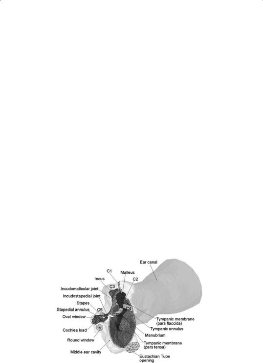
Fig.1FEmodelofhumanleftearincludingtheTM,threeossicles(malleus,incus,and stapes), two joints and manubrium, ligaments and muscle tendons (C1, C2, C3, C4, C5, C7), tympanic annulus, stapedial annular ligament, external ear canal, middle ear cavity, and cochlear load, in anterior-medial view. The middle ear cavity was assumed transparent.

Modeling of sound transmission from the ear canal through the middle ear to cochlea requires multi-field coupled analysis. The air in the ear canal and inside the middle ear cavity was modeled as acoustic elements and governed by the simplified acoustic wave equation under the assumption that the fluid is compressible and inviscid with uniform mean density and pressure. The surface of acoustic elements next to the movable structure such as the TM, ossicles, and suspensory ligaments, was defined as fluid-structural interface (FSI) where the acoustic pressure distribution was coupled into structural analysis in ANSYS.
2.2 Measurement of middle ear transfer function in human temporal bones
Seven fresh-frozen cadaver temporal bones (3 male, 4 female, average age 69.4) were used in this study. The preparation of temporal bone specimen and sound delivery system were almost the same as that reported in our previous paper [3]. After facial recess on the bone, 90 dB pure tone sound signals were delivered to the TM by an insert earphone and monitored by a probe microphone placed in the canal approximately 2 mm away from the umbo. The second probe microphone was placed between the round window and stapes for measuring the middle ear pressure. The middle ear cavity was then covered by a piece of glass and closed by filling dental cement. Two laser vibrometers (Polytec, HLV-1000 and OFV 501) were used to measure vibrations of the TM and stapes simultaneously with one laser focusing on the umbo and another focusing on the stapes footplate.
The control experiment was performed first to measure the normal middle ear function. After control data were collected, two types of TM perforation were created in the temporal bones and simulated in the FE model as shown in Fig. 2. The perforation Case #1 was made in the infe- rior-posterior site of the TM with a perforation area of 1.4 mm2. The perforation Case #2 was made in the inferior site with an area of 1.0 mm2. The 207 laser measurements of the umbo and footplate were conducted on Case
#1 first and then the perforation Case #2 was made and the hole in the inferior-posterior site of the TM was patched with cigarette paper. Finally, the paper was removed and measurement was made with combination of Cases #1 and #2.