


44 |
Chapter 3 |
H. Posterior Ethmoid Air Cells (Figures 26 and 27)
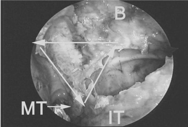
The posterior ethmoid cells may be entered safely through the most horizontal portion of the middle turbinate lamella. Endoscopically visuale an imaginary line perpendicular to the nasal septum from the posterior MOF, another line along the vertical antrostomy ridge, and a third along the free edge of the middle turbinate basal lamella, forming a triangle. The triangle demarcates the zone of safe entry into the inferior aspect of the posterior ethmoid sinus (i.e., through the horizontal portion of the middle turbinate’s basal lamella) (37).
Once the lateral (orbital) wall of the posterior ethmoid has been identified, the surgeon may proceed with further dissection of the superior cell(s) of the posterior ethmoid or suprabullar area, thus completing the total ethmoidectomy. The vertical portion of the middle turbinate basal lamella more anterosuperiorly, or other ethmoid septations are carefully removed in a posteroanterior and superoinferior direction. Initially, the surgeon restricts the dissection to an area adjacent to the orbital wall and lateral ethmoid roof where the bone is thickest. Additional passes along the medial ethmoid roof are then performed to open up more medially located cells, once the roof of
(a)
Figure 26 Sagittal (a) and endoscopic (b) views denoting the triangular zone of safe entry (asterisk) into the inferior posterior ethmoid through the horizontal portion of the basal lamella (solid line). MT = tail of the middle turbinate. B = area of ethmoid bulla. IT = inferior turbinate.
Basic Dissection |
45 |
the ethmoid is identified laterally. The surgeon should observe that the roof of the anterior ethmoid roof slopes medially by as much as 45 degrees.
The mucosa along the orbital wall and ethmoid roof is left undisturbed, whenever possible, to avoid granulations, osteitis, prolonged healing, osteoneogenesis, and fibrosis. Only the mucosa overlying the septations is removed. This can be facilitated by the use of cutting forceps or powered instrumentation.
(b)

46 |
Chapter 3 |
(a)
Figure 27 Sagittal (a) and endoscopic (b) views after removal of the middle turbinate basal lamella. The vertical portion of the basal lamella (arrows) separates the superior aspect of the posterior ethmoid from the suprabullar air cells. PE = posterior ethmoid. B = area of ethmoid bulla.

Basic Dissection |
47 |
(b)

48 |
Chapter 3 |
I.Sphenoid Sinusotomy (Figures 28–34)
The sphenoid ostium is located medial to the tail of the superior and supreme turbinate and adjacent to the nasal septum, approximately 7 cm from the nasolabial angle of the columnella (37). This area corresponds to the middle third of the sphenoid sinus’ vertical height.
A direct sphenoid sinusotomy may be performed without performing an ethmoidectomy or antrostomy. The superior turbinate is exposed endoscopically by reducing the middle turbinate head (as previously described). With a straight ball probe or Cottle periosteal elevator, the surgeon gently palpates the area immediately adjacent to the tail of the superior turbinate and then progresses further superiorly until the sphenoid sinus is entered and the posterior wall is palpated. The posterior wall of sphenoid sinus measures approximately 9 cm from the base of the columnella. The sphenoid is initially opened inferiorly and medially with a sphenoid punch or powered instrumentation. The sphenoid ostium is enlarged laterally only after confirming an aircontaining space behind its common wall with the posterior ethmoid sinus. Blind removal, without confirming an air-containing space, can result in inadvertent injury to the intrasphenoidal carotid artery.
(a)
Figure 28 Sagittal (a) and endoscopic (b) view showing a probe through the natural ostium of the sphenoid sinus (S), which lies adjacent to the nasal septum (NS) and superomedial to the tail of the superior turbinate (ST).

Basic Dissection |
49 |
When significant anatomical distortion exists in the area of the sphenoethmoidal recess, and the posterior insertion of the superior turbinate is not clearly visible, then the MOF is used to determine the approach into the sphenoid sinus. In these situations, the sphenoid sinus is entered and identified medially adjacent to the nasal septum, approximately 7 cm from the base of the columnella, at the level of the posterior MOF along the horizontal ridge of the antrostomy. When the posterior MOF is used, the sphenoid sinus will be entered consistently in its inferior to middle third. In most cases, this area also corresponds to the location of the sphenoid ostium. If the maxillary natural ostium (or anterior antrostomy ridge) is used as a reference point, then the sphenoid will be entered slightly more inferiorly, where thicker bone may be encountered. Entering the sphenoid medially, through the area of its natural ostium, obviates the possibility of inadvertent injury to the intrasphenoid carotid artery located more laterally. The latter may occur when a blind transethmoidal entry into the sphenoid sinus, lateral to the tail of the superior turbinate, is performed. Entering the sphenoid medially permits enlargement of the normal sphenoid ostium, thus restoring the normal mucociliary flow of the sphenoid sinus. It also minimizes the chance of creating a separate drainage area through the back wall of the posterior ethmoid sinus.
(b)

50 |
Chapter 3 |
(a)
Figure 29 Sagittal (a) and endoscopic (b) views showing the approximate level of entry into the sphenoid sinus if the posterior MOF (solid arrow) versus the anterior MOF (dotted arrow) are used. Using the posterior MOF will guide the surgeon into the middle third of the sphenoid sinus (S). This corresponds to the area of the sphenoid natural ostium. The anterior MOF or maxillary natural ostium area will guide the surgeon slightly more inferiorly through harder bone, into the inferior third of the sphenoid. The dotted line represents the posterosuperior angulation of the orbital floor toward the orbital apex. PE = posterior ethmoid.

Basic Dissection |
51 |
(b)
52 |
Chapter 3 |
Figure 30 Sagittal view showing the usual trajectory of dissection when the MOF and antrostomy ridge are kept in view at all times.

Basic Dissection |
53 |
Figure 31 Sagittal view showing the columnellar measurements to the anterior face of the posterior ethmoid (horizontal portion of the middle turbinate basal lamella) at the MOF level (dotted arrow). This measurement is approximately 5 cm. The solid arrow denotes the columnellar measurement to the anterior face of the sphenoid sinus (S) or posterior wall of the posterior ethmoid sinus (PE) at the MOF level. This measurement is generally around 7 cm.

54 |
Chapter 3 |
Figure 32 Endoscopic view showing the sphenoid ostium (asterisk), which has been enlarged inferiorly and medially. ST = superior turbinate. MT = middle turbinate. PE = posterior ethmoid. M = maxillary sinus. Arrows denote the antrostomy ridge.
Figure 33 Sagittal (a) and endoscopic (b) views after completion of sphenoethmoidectomy. The sphenoid ostium has also been enlarged medially and inferiorly toward its floor. The common wall between the sphenoid (S) and posterior ethmoid (PE) has been removed. Note the relationship of these cavities to the MOF (arrow). Most of the posterior ethmoid cavity is located above this line. Conversely, most of the sphenoid is located below this line. MT = tail of middle turbinate. B = area of ethmoid bulla. I = infundibular wall.

Basic Dissection |
55 |
(a)
(b)

56 |
Chapter 3 |
(a)
Figure 34 Sagittal (a) and endoscopic (b) views illustrating the relationship between the horizontal (black dotted line) and vertical (white dotted line) ridge of the antrostomy and the adjacent anterior ethmoid or ethmoid (B) and the posterior ethmoid sinus (PE). The transition area (solid white line) between the horizontal and vertical ridge represents the approximate level where the posterior ethmoid is entered more laterally to this point, through the horizontal portion of the middle turbinate basal lamella.

Basic Dissection |
57 |
(b)

58 |
Chapter 3 |
J.Frontal Sinusotomy (Figures 35 and 36)
The frontal sinus is identified by drawing a line parallel to the bony nasolacrimal duct and directed superiorly from the anterior border of the antrostomy (i.e., natural ostium area) to a point 5 to 10 mm behind the anterior attachment (axilla) of the middle turbinate. The correct point of entry will be directed superomedially away from the wall of the orbit and anteriorly away from the anterior ethmoid artery. The anterior ethmoid artery is located an average of 20 mm (range 17–25 mm) from the anterior attachment of the middle turbinate (50).
Palpation of the frontal sinus’ posterior wall is the key to identifying the frontal sinus and opening the frontal sinus ostium. The septations that comprise the roof of the suprabullar cells, and the agger nasi or frontal cells, are gently displaced anteroinferiorly with the angled probe to avoid
(a)
Figure 35 Sagittal (a) and endoscopic (b) views after uncinectomy and identification of the maxillary natural ostium. The frontal recess is identified by drawing a line (solid arrow) parallel to the bony nasolacrimal duct (oval) and directed superiorly from the natural ostium area to a point 5 to 10 mm behind the anterior attachment of the middle turbinate (asterisk). The correct point of entry will be directed superomedially away from the wall of the orbit and adjacent to the middle turbinate vertical lamella (MT). B = area of the ethmoid bulla. I = lateral wall of the infundibulum. IT = inferior turbinate.

Basic Dissection |
59 |
inadvertent penetration into the anterior cranial fossa at the level of the anterior ethmoid artery. An upbiting forceps or giraffe forceps is used to carefully collect the bony fragments. As with the ethmoid, maxillary, and sphenoid sinuses, an attempt is made to preserve as much as possible of the frontal recess and frontal ostium mucosa circumferentially to diminish the chance of prolonged healing, fibrosis, or osteoneogenesis, and subsequent ostial stenosis or complete closure. Throughcut forceps or powered instrumentation with angled cannulas can be used effectively for this purpose. In the presence of osteoneogenesis or fibrosis, more advanced endoscopic procedures may be required (see Section G below).
Transillumination can be used to confirm one’s position in the frontal sinus. When the frontal sinus is correctly identified the telescope’s light will transilluminate the frontal area. A supraorbital extension of an ethmoid cell will transilluminate in the medial canthal area.
(b)

60 |
Chapter 3 |
(a)
Figure 36 Sagittal (a) and endoscopic (b) views after completion of total ethmoidectomy and maxillary antrostomy. The frontal sinus is identified by drawing a line (solid arrow) parallel to the bony nasolacrimal duct (oval) and directed superiorly from the anterior border of the antrostomy or maxillary sinus natural ostium area to a point 5 to 10 mm behind the anterior attachment of the middle turbinate (asterisk). The correct point of entry will be directed superomedially away from the wall of the orbit and anteriorly away from the anterior ethmoid artery (AA). S = sphenoid sinus. PE = area of the posterior ethmoid sinus. B = area of the ethmoid bulla. I = infundibular area. M = maxillary sinus. PA = posterior ethmoid artery.

Basic Dissection |
61 |
(b)
This Page Intentionally Left Blank