
- •ISBN: 0-8247-0743-5
- •Contents
- •Preface
- •2. Surgical Instrumentation, Setup, and Patient Positioning
- •3. Basic Dissection
- •D. Middle Turbinoplasty
- •G. Anterior Ethmoid Air Cells
- •H. Posterior Ethmoid Air Cells
- •4. Advanced Dissections
- •D. Orbital Decompression
- •G. Extended Frontal Sinusotomy and the Lothrop Procedure
- •H. Extended Maxillary Antrostomy and Medial Maxillectomy
- •References
- •Index
2
Surgical Instrumentation, Setup, and Patient Positioning
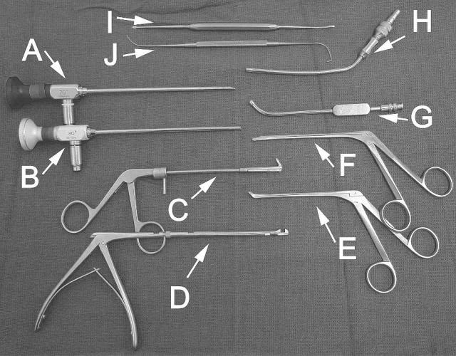
A.Surgical Instrumentation (Figures 3 and 4)
Very few instruments are actually required to perform ESS. However, as one gains more surgical experience, there may be a need for additional instrumentation depending on the type of procedure or on the surgeon’s personal preferences. The minimum instrumentation required for most of the dissections in this manual include: 1) a 30-degree telescope, 2) a 360-degree backbiting forceps, 3) a 360-degree sphenoid punch or forceps, 4) a 4-mm-long curved suction, 5) a 10 or 12 French straight (Frazier) suction with calibrated centimeter markings, 6) a 3.5-mm straight through-cut forceps, 7) a 3.5-mm upbiting through-cut forceps, 8) a small angled ball probe, and 9) a Cottle periosteal elevator. Powered instrumentation with a 4-mm straight and/or 60-degree cannula can be used in lieu of forceps to perform an ethmoidectomy and multiple sinusotomies.
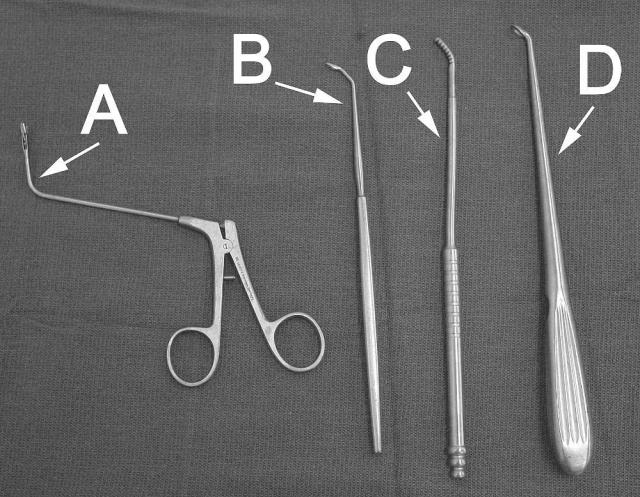
For more advanced procedures, a 70-degree telescope is useful to visualize lateral or superior recesses of the frontal, maxillary, or sphenoid sinus. Curettes of various sizes are useful for removing thick bone, especially around the frontal ostium or sphenoid rostrum. Powered instrumentation with cutting or diamond burrs may also be necessary to carefully remove bone around critical structures such as the lacrimal sac, skull base, optic nerve, or carotid artery.
9
10 |
Chapter 2 |
Figure 3 Minimum instrumentation required for ESS. A = 30-degree telescope. B = 70-degree telescope (optional). C = 360-degree backbiting forceps. D = 360-degree sphenoid punch or forceps. E = 3.5-mm upbiting through-cut forceps. F = 3.5-mm straight through-cut forceps. G = 4 mm long curved suction. H = calibrated straight (Frazier) suction. I = Cottle periosteal elevator. J = ostium seeker or ball probe, which is angled at one end and curved at the other.
Instrumentation and Preparation |
11 |
Figure 4 Additional instrumentation required for bone and tissue removal around the frontal ostium or sphenoid rostrum area. These instruments can be useful when performing an extended frontal or sphenoid sinusotomy. A = giraffe forceps. B = frontal curette. C = frontal rasp. D = angled cervical spine curette.
12 |
Chapter 2 |
B.OR Setup and Patient Positioning (Figures 5–10)
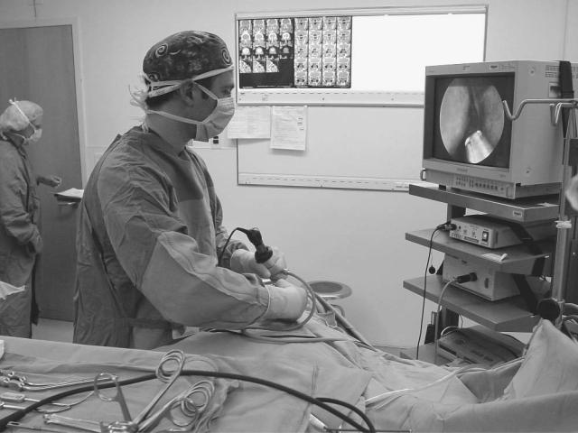
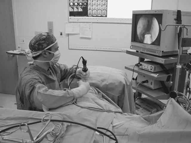
The surgeon should be sitting or standing comfortably at the patient’s side. A right-handed surgeon typically stands on the right side of the patient and a left-handed surgeon stands on the left side of the patient. If the surgeon chooses to sit, then a Mayo stand (cushioned with a pillow) is used to rest the arm holding the telescope at a comfortable height over the patient’s head. The video tower and any intraoperative imaging devices are positioned at the head of the table, facing the surgeon.
A clear adhesive dressing (e.g., OpSite) is placed over the eye for protection. This allows the surgeon to visualize and palpate the eyes during the surgical procedure. The patient’s face is draped to expose only the forehead, eyes, nose, and upper lip. The mouth and endotracheal tube are typically draped out unless a concomitant sublabial or oral procedure is planned.
The manner in which the telescope is grasped or instrumentation introduced into the nose may vary depending on the surgeon’s personal preference, the specific length and type of telescope
Figure 5 Standing position.
Instrumentation and Preparation |
13 |
Figure 6 Sitting position, resting the elbow on a Mayo stand.
and/or camera, and the specific anatomical area being addressed. Generally, the surgeon determines which manner is best suited for his or her own hand.
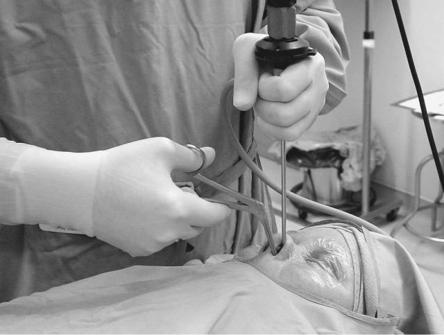
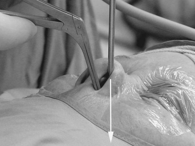
A 30-degree telescope looking laterally is all that is typically necessary for most of the dissections described in this manual. A 0-degree telescope may also be used, but may limit adequate visualization of the lateral nasal structures (i.e., maxillary natural ostium, maxillary sinus, supraorbital ethmoidal cells, etc.). The axis of the telescope is directed toward the occipital area of the head and the superior border of the inferior turbinate is kept in view during the initial part of the procedure until the medial orbital floor is identified through the antrostomy. This keeps the surgeon directed toward the choanal arch and superior nasopharynx. The telescope is positioned at the nasoseptal angle with gentle superior retraction of the nasal tip and the surgical instrumentation is inserted inferior to the telescope.
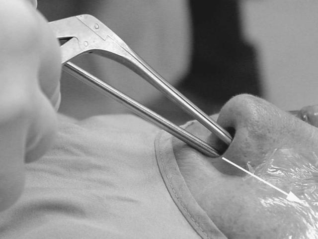
A 70-degree telescope can be used if further visualization is required into the superior or lateral recesses of the frontal, maxillary, or sphenoid sinus. The 30-degree or 70-degree telescope is placed along the floor of the vestibule looking superiorly (as when working around the frontal ostium) or medially (as when performing a septoplasty). In these cases, the instruments are introduced superior to the telescope.
14 |
Chapter 2 |
Figure 7 The telescope is grasped comfortably and the instrumentation is introduced inferior to the telescope for most of the procedures.
Instrumentation and Preparation |
15 |
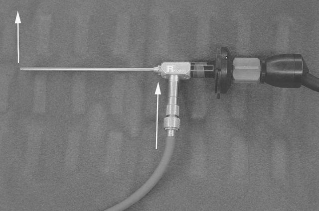
Figure 8 The direction that the surgeon is visualizing through an angled telescope corresponds to the direction in which the fiberoptic light cable enters the telescope (arrows). This is one way the surgeon can tell which direction he or she is looking at while performing ESS.
16 |
Chapter 2 |
Figure 9 For most of the dissections the 30-degree telescope is directed toward the patient’s occipital area (arrow), with gentle superior retraction of the nasal tip and ala.
Instrumentation and Preparation |
17 |
Figure 10 The instrumentation is introduced superior to the telescope when working around the frontal ostium.
This Page Intentionally Left Blank
