

Курсовая работа по РЗА / Терминалы / каталоги / 7SJ61xx_Catalog_SIP-2008_en
.pdfSIPROTEC 4 7SJ61
Multifunction Protection Relay
LSP2299-afpen.eps
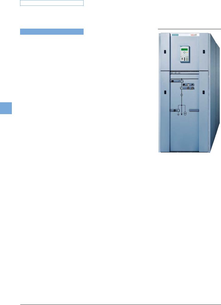
Fig. 5/78 SIPROTEC 4 7SJ61 multifunction protection relay
Description
The SIPROTEC 4 7SJ61 relays can be used for line protection of high and medium voltage networks with earthed (grounded), low-resistance earthed, isolated or compensated neutral point. When protecting motors, the SIPROTEC 4 7SJ61 is suitable for asynchronous machines of all sizes. The relay performs all functions of backup protection supplementary to transformer differential protection.
The relay provides control of the circuitbreaker, further switching devices and automation functions. The integrated programmable logic (CFC) allows the user to implement their own functions, e. g. for the automation of switchgear (interlocking). The user is also allowed to generate user-defined messages.
The flexible communication interfaces are open for modern communication architectures with control systems.
5 Overcurrent Protection / 7SJ61
Function overview
Protection functions
•Time-overcurrent protection (definite-time/inverse-time/user-def.)
•Sensitive earth-fault detection
•Intermittent earth-fault protection
•High-impedance restricted earth fault
•Inrush restraint
•Motor protection
–Undercurrent monitoring
–Starting time supervision
–Restart inhibit
–Locked rotor
– Load jam protection |
5 |
•Overload protection
•Temperature monitoring
•Breaker failure protection
•Negative-sequence protection
•Auto-reclosure
•Lockout
Control functions/programmable logic
•Commands for control of a circuit-breaker and of isolators
•Control via keyboard, binary inputs, DIGSI 4 or SCADA system
•User-defined logic with CFC (e.g. interlocking)
Monitoring functions
•Operational measured values I
•Circuit-breaker wear monitoring
•Slave pointer
•Time metering of operating hours
•Trip circuit supervision
•8 oscillographic fault records
•Motor statistics
Communication interfaces
•System interface
–IEC 60870-5-103, IEC 61850
–PROFIBUS-FMS/-DP
–DNP 3.0/MODBUS RTU
•Service interface for DIGSI 4 (modem)
•Front interface for DIGSI 4
•Time synchronization via IRIG B/DCF77
Hardware
•4 current transformers
•3/8/11 binary inputs
•4/8/6 output relays
Siemens SIP · 2008 |
5/77 |
5 Overcurrent Protection / 7SJ61 |
Application |
5 |
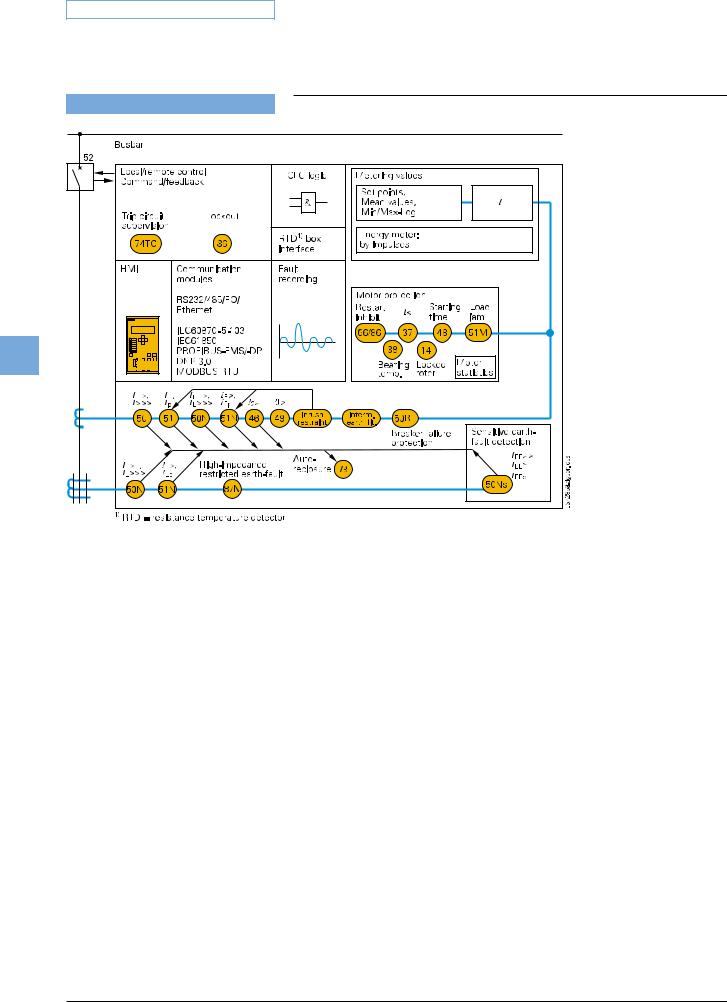
Fig. 5/79 Function diagram
The SIPROTEC 4 7SJ61 unit is a numerical protection relay that also performs control and monitoring functions and therefore supports the user in cost-effective power system management, and ensures reliable supply of electric power to the customers. Local operation has been designed according to ergonomic criteria. A large, easy-to-read display was a major design aim.
Control
The integrated control function permits control of disconnect devices, earthing switches or circuit-breakers via the integrated operator panel, binary inputs, DIGSI 4 or the control and protection system (e.g. SICAM). A full range of command processing functions is provided.
Programmable logic
The integrated logic characteristics (CFC) allow the user to implement their own functions for automation of switchgear (interlocking) or a substation via a graphic user interface. The user can also generate userdefined messages.
Line protection
The relay is a non-directional overcurrent relay which can be used for line protection of high and medium-voltage networks with earthed (grounded), low-resistance earthed, isolated or compensated neutral point.
Motor protection
When protecting motors, the 7SJ61 relay is suitable for asynchronous machines of all sizes.
Transformer protection
The relay performs all functions of backup protection supplementary to transformer differential protection. The inrush suppression effectively prevents tripping by inrush currents.
The high-impedance restricted earth-fault protection detects short-circuits and insulation faults on the transformer.
Backup protection
The 7SJ61can be used universally for backup protection.
Flexible protection functions
By configuring a connection between a standard protection logic and any measured or derived quantity, the functional scope of the relays can be easily expanded by up to 20 protection stages or protection functions.
Metering values
Extensive measured values, limit values and metered values permit improved system management.
5/78 |
Siemens SIP · 2008 |
Application
ANSI No. |
IEC |
50, 50N |
I>, I>>, I>>> |
|
IE>, IE>>, IE>>> |
51, 51N |
Ip, IEp |
50Ns, 51Ns |
IEE>, IEE>>, IEEp |
– |
|
– |
IE> |
87N |
|
50BF |
|
79 |
|
46 |
I2> |
49 |
ϑ> |
48 |
|
51M |
|
14 |
|
66/86 |
|
37 |
I< |
38 |
|
Construction
Connection techniques and housing with many advantages
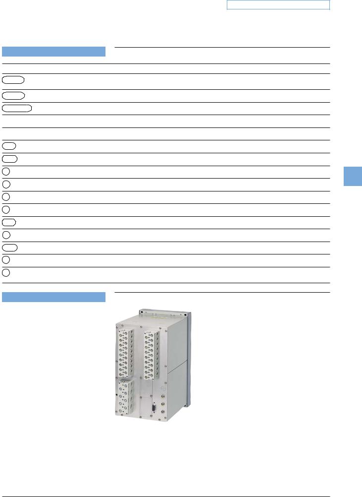
1/3-rack sizes is the available housing width of the 7SJ61 relays, referred to a 19” module frame system. This means that previous models can always be replaced. The height is a uniform 244 mm for flushmounting housings and 266 mm for sur- face-mounting housing. All cables can be connected with or without ring lugs.
In the case of surface mounting on a panel, the connection terminals are located above and below in the form of screw-type terminals. The communication interfaces are located in a sloped case at the top and bottom of the housing.
5 Overcurrent Protection / 7SJ61
Protection functions
Definite-time overcurrent protection (phase/neutral)
Inverse-time overcurrent protection (phase/neutral) |
|
Sensitive earth-fault protection |
|
Cold load pick-up (dynamic setting change) |
|
Intermittent earth fault |
|
High-impedance restricted earth-fault protection |
|
Breaker failure protection |
|
Auto-reclosure |
|
Phase-balance current protection (negative-sequence protection) |
5 |
Thermal overload protection |
|
Starting time supervision
Load jam protection
Locked rotor protection
Restart inhibit
Undercurrent monitoring
Temperature monitoring via external device (RTD-box), e.g. bearing temperature monitoring
LSP2099-afpen.eps
Fig. 5/80 Rear view with screw-type terminals
Siemens SIP · 2008 |
5/79 |

5 Overcurrent Protection / 7SJ61
Protection functions
Time-overcurrent protection (ANSI 50, 50N, 51, 51N)
This function is based on the phase-selective measurement of the three phase currents and the earth current (four transformers). Three definite-time overcurrent protection elements (DMT) exist both for the phases and for the earth. The current threshold and the delay time can be set within a wide range. In addition, inverse-time overcurrent protection characteristics (IDMTL) can be activated.
5 |
|
|
Fig. 5/81 |
|
Fig. 5/82 |
|
|
|
|
||
|
|
|
Definite-time overcurrent protection |
Inverse-time overcurrent protection |
|
|
|
Available inverse-time characteristics |
|
|
|
|
|
|
|
|
|
|
|
Characteristics acc. to |
ANSI/IEEE |
IEC 60255-3 |
|
|
|
|
|
|
|
|
|
Inverse |
• |
• |
|
|
|
|
|
|
|
|
|
Short inverse |
• |
|
|
|
|
|
|
|
|
|
|
Long inverse |
• |
• |
|
|
|
|
|
|
|
|
|
Moderately inverse |
• |
|
|
|
|
|
|
|
|
|
|
Very inverse |
• |
• |
|
|
|
|
|
|
|
|
|
Extremely inverse |
• |
• |
|
|
|
|
|
|
|
Reset characteristics
For easier time coordination with electromechanical relays, reset characteristics according to ANSI C37.112 and
IEC 60255-3 / BS 142 standards are applied. When using the reset characteristic (disk emulation), a reset process is initiated after the fault current has disappeared. This reset process corresponds to the reverse movement of the Ferraris disk of an electromechanical relay (thus: disk emulation).
User-definable characteristics
Instead of the predefined time characteristics according to ANSI, tripping characteristics can be defined by the user for phase and earth units separately. Up to 20 current/ time value pairs may be programmed. They are set as pairs of numbers or graphically in DIGSI 4.
Inrush restraint
The relay features second harmonic restraint. If the second harmonic is detected during transformer energization, pickup of non-di- rectional normal elements (I>, Ip) are blocked.
Cold load pickup/dynamic setting change
For time-overcurrent protection functions the initiation thresholds and tripping times can be switched via binary inputs or by time control.
Flexible protection functions
The 7SJ61 units enable the user to easily add on up to 20 protective functions. To this end, parameter definitions are used to link a standard protection logic with any chosen characteristic quantity (measured or derived quantity). The standard logic consists of the usual protection elements such as the pickup message, the parameterdefinable delay time, the TRIP command, a blocking possibility, etc. The mode of operation for current quantities can be three-phase or single-phase. The quantities can be operated as greater than or less than stages. All stages operate with protection priority. Protection stages/functions attainable on the basis of the available characteristic quantities:
Function |
ANSI No. |
I>, IE> |
50, 50N |
|
|
3I0>, I1>, I2>, I2/I1> |
50N, 46 |
|
|
Binary input |
|
5/80 |
Siemens SIP · 2008 |
Protection functions
(Sensitive) earth-fault detection (ANSI 50Ns, 51Ns/50N, 51N)
For high-resistance earthed networks, a sensitive input transformer is connected to a phase-balance neutral current transformer (also called core-balance CT).
The function can also be operated in the insensitive mode as an additional shortcircuit protection.
Intermittent earth-fault protection
Intermittent (re-striking) faults occur due to insulation weaknesses in cables or as a result of water penetrating cable joints. Such faults either simply cease at some stage or develop into lasting short-circuits. During intermittent activity, however, star-point resistors in networks that are impedance-earthed may undergo thermal overloading. The normal earth-fault protection cannot reliably detect and interrupt the current pulses, some of which can be very brief.
The selectivity required with intermittent earth faults is achieved by summating the duration of the individual pulses and by triggering when a (settable) summed time is reached. The response threshold IIE> evaluates the r.m.s. value, referred to one systems period.
Breaker failure protection (ANSI 50BF)
If a faulted portion of the electrical circuit is not disconnected upon issuance of a trip command, another command can be initiated using the breaker failure protection which operates the circuit-breaker, e.g. of an upstream (higher-level) protection relay. Breaker failure is detected if after a trip command, current is still flowing in the faulted circuit. As an option it is possible to make use of the circuit-breaker position indication.
Phase-balance current protection (ANSI 46) (Negative-sequence protection)
In line protection, the two-element phasebalance current/negative-sequence protection permits detection on the high side of high-resistance phase-to-phase faults and phase-to-earth faults that are on the low side of a transformer (e.g. with the switch group Dy 5). This provides backup protection for high-resistance faults beyond the transformer.
Settable dropout delay times
If the devices are used in parallel with electromechanical relays in networks with intermittent faults, the long dropout times of the electromechanical devices (several hundred milliseconds) can lead to problems in terms of time grading. Clean time grading is only possible if the dropout time is approximately the same. This is why the parameter of dropout times can be defined for certain functions such as time-overcurrent protection, earth short-circuit and phase-balance current protection.
Auto-reclosure (ANSI 79)
Multiple reclosures can be defined by the user and lockout will occur if a fault is present after the last reclosure. The following functions are possible:
•3-pole ARC for all types of faults
•Separate settings for phase and earth faults
•Multiple ARC, one rapid auto-reclosure (RAR) and up to nine delayed autoreclosures (DAR)
•Starting of the ARC depends on the trip command selection (e.g. 46, 50, 51)
•Blocking option of the ARC via binary inputs
•ARC can be initiated externally or via CFC
•The overcurrent elements can either be blocked or operated non-delayed depending on the auto-reclosure cycle
•Dynamic setting change of the overcurrent elements can be activated depending on the ready AR
Thermal overload protection (ANSI 49)
For protecting cables and transformers, an overload protection with an integrated pre-warning element for temperature and current can be applied. The temperature is calculated using a thermal homogeneousbody model (according to IEC 60255-8), which takes account both of the energy en-
tering the equipment and the energy losses. The calculated temperature is constantly adjusted accordingly. Thus, account is taken of the previous load and the load fluctuations.
For thermal protection of motors (especially the stator) a further time constant can be set so that the thermal ratios can be detected correctly while the motor is rotating and when it is stopped. The ambient temperature or the temperature of the coolant can be detected serially via an external temperature monitoring box (resis- tance-temperature detector box, also called RTD-box). The thermal replica of the
5 Overcurrent Protection / 7SJ61
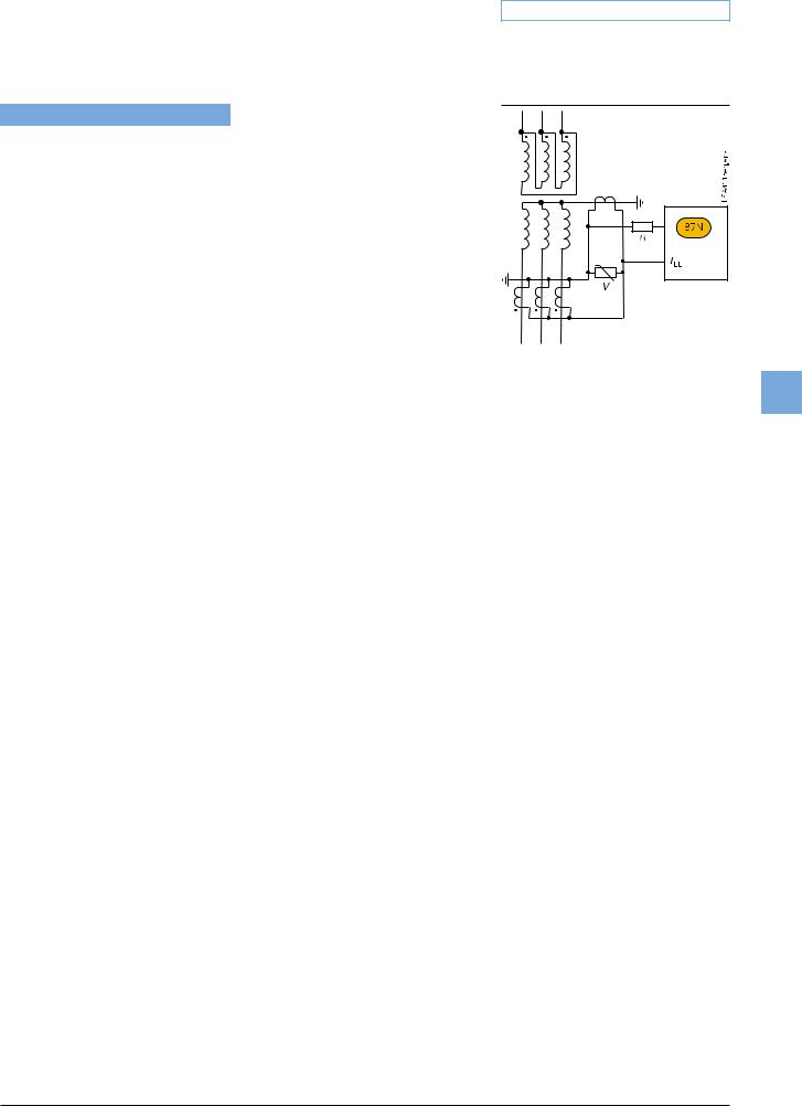
Fig. 5/83 High-impedance restricted earthfault protection
5
overload function is automatically adapted to the ambient conditions. If there is no RTD-box it is assumed that the ambient temperatures are constant.
High-impedance restricted earth-fault protection (ANSI 87N)
The high-impedance measurement principle is an uncomplicated and sensitive method for detecting earth faults, especially on transformers. It can also be applied to motors, generators and reactors when these are operated on an earthed network.
When the high-impedance measurement principle is applied, all current transformers in the protected area are connected in parallel and operated on one common resistor of relatively high R whose voltage is measured (see Fig. 5/83). In the case of 7SJ6 units, the voltage is measured by detecting the current through the (external) resistor R at the sensitive current measurement input IEE. The varistor V serves to limit the voltage in the event of an internal fault. It cuts off the high momentary voltage spikes occurring at transformer saturation. At the same time, this results in smoothing of the voltage without any noteworthy reduction of the average value. If no faults have occurred and in the event of external faults, the system is at equilibrium, and the voltage through the resistor is approximately zero. In the event of internal faults, an imbalance occurs which leads to a voltage and a current flow through the resistor R.
The current transformers must be of the same type and must at least offer a separate core for the high-impedance restricted earth-fault protection. They must in particular have the same transformation ratio and an approximately identical knee-point voltage. They should also demonstrate only minimal measuring errors.
Siemens SIP · 2008 |
5/81 |
5 Overcurrent Protection / 7SJ61
Protection functions/Functions
Motor protection
Starting time supervision (ANSI 48)
Starting time supervision protects the motor against long unwanted start-ups that might occur when excessive load torque occurs, excessive voltage drops occur within the motor or if the rotor is locked. Rotor temperature is calculated from measured stator current. The tripping time is calculated according to the following equation:
|
for I > IMOTOR START |
||||
|
|
I A |
2 |
||
|
t = |
|
|
TA |
|
|
|
||||
|
|
I |
|
||
5 |
I |
|
|
= Actual current flowing |
|
IMOTOR START = Pickup current to detect a motor |
|||||
|
|||||
|
|
|
|
start |
|
|
t |
|
|
= Tripping time |
|
|
IA |
|
|
= Rated motor starting current |
|
|
TA |
|
|
= Tripping time at rated motor |
|
|
|
|
|
starting current (2 times, |
|
|
|
|
|
for warm and cold motor) |
|
The characteristic (equation) can be adapted optimally to the state of the motor by applying different tripping times TA in dependence of either cold or warm motor state. For differentiation of the motor state the thermal model of the rotor is applied.
If the trip time is rated according to the above formula, even a prolonged start-up and reduced voltage (and reduced start-up current) will be evaluated correctly. The tripping time is inverse (current dependent).
A binary signal is set by a speed sensor to detect a blocked rotor. An instantaneous tripping is effected.
Temperature monitoring (ANSI 38)
Up to 2 temperature monitoring boxes with a total of 12 measuring sensors can be used for temperature monitoring and detection by the protection relay. The thermal status of motors, generators and transformers can be monitored with this device. Additionally, the temperature of the bearings of rotating machines are monitored for limit value violation. The temperatures are being measured with the help of temperature detectors at various locations of the device to be protected. This data is transmitted to the protection relay via one or two temperature monitoring boxes (see “Accessories”, page 5/100).
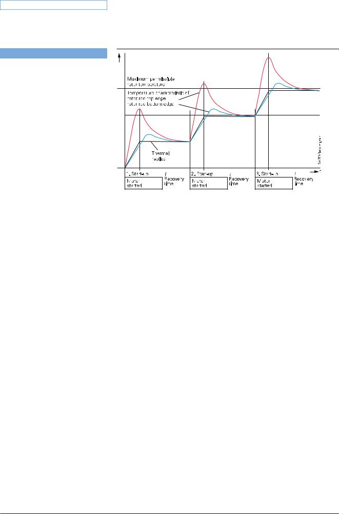
Fig. 5/84
Load jam protection (ANSI 51M)
Sudden high loads can cause slowing down and blocking of the motor and mechanical damages. The rise of current due to a load jam is being monitored by this function (alarm and tripping). The overload protection function is too slow and therefore not suitable under these circumstances.
Phase-balance current protection (ANSI 46) (Negative-sequence protection)
The negative-sequence / phase-balance current protection detects a phase failure or load unbalance due to network asymmetry and protects the rotor from impermissible temperature rise.
Restart inhibit (ANSI 66/86)
If a motor is started up too many times in succession, the rotor can be subject to thermal overload, especially the upper edges of the bars. The rotor temperature is calculated from the stator current. The reclosing lockout only permits start-up of the motor if the rotor has sufficient thermal reserves for a complete startup (see Fig. 5/84).
Emergency start-up
This function disables the reclosing lockout via a binary input by storing the state of the thermal replica as long as the binary input is active. It is also possible to reset the thermal replica to zero.
Undercurrent monitoring (ANSI 37)
With this function, a sudden drop in current, that can occur due to a reduced motor load, is detected. This may be due to shaft breakage, no-load operation of pumps or fan failure.
Motor statistics
Essential information on start-up of the motor (duration, current, voltage) and general information on number of starts, total operating time, total down time, etc. are saved as statistics in the device.
Circuit-breaker wear monitoring
Methods for determining circuit-breaker contact wear or the remaining service life of a circuit-breaker (CB) allow CB maintenance intervals to be aligned to their actual degree of wear. The benefit lies in reduced maintenance costs.
There is no mathematically exact method of calculating the wear or the remaining service life of circuit-breakers that takes into account the arc-chamber's physical conditions when the CB opens. This is why various methods of determining CB wear have evolved which reflect the different operator philosophies. To do justice to these, the devices offer several methods:
• I
I
•Σ I x, with x = 1... 3
•Σ i 2t
The devices additionally offer a new method for determining the remaining service life:
• Two-point method
5/82 |
Siemens SIP · 2008 |

Protection functions/Functions
The CB manufacturers double-logarithmic switching cycle diagram (see Fig. 5/85) and the breaking current at the time of contact opening serve as the basis for this method. After CB opening, the two-point method calculates the number of still possible switching cycles. To this end, the two points P1 and P2 only have to be set on the device. These are specified in the CB's technical data.
All of these methods are phase-selective and a limit value can be set in order to obtain an alarm if the actual value falls below or exceeds the limit value during determination of the remaining service life.
Commissioning
Commissioning could hardly be easier and is fully supported by DIGSI 4. The status of the binary inputs can be read individually and the state of the binary outputs can be set individually. The operation of switching elements (circuit-breakers, disconnect devices) can be checked using the switching functions of the bay controller. The analog measured values are represented as wide-ranging operational measured values.
To prevent transmission of information to the control center during maintenance, the bay controller communications can be disabled to prevent unnecessary data from being transmitted. During commissioning, all indications with test marking for test purposes can be connected to a control and protection system.
Test operation
During commissioning, all indications can be passed to an automatic control system for test purposes.
Control and automatic functions
Control
In addition to the protection functions, the SIPROTEC 4 units also support all control and monitoring functions that are required for operating medium-voltage or highvoltage substations.
The main application is reliable control of switching and other processes.
5 Overcurrent Protection / 7SJ61
The status of primary equipment or auxiliary devices can be obtained from auxiliary contacts and communicated to the 7SJ61 via binary inputs. Therefore it is possible to detect and indicate both the OPEN and CLOSED position or a fault or intermediate circuit-breaker or auxiliary contact position.
The switchgear or circuit-breaker can be controlled via:
–integrated operator panel
–binary inputs
–substation control and protection system
–DIGSI 4
Automation / user-defined logic
With integrated logic, the user can set, via a graphic interface (CFC), specific functions for the automation of switchgear or substation. Functions are activated via function keys, binary input or via communication interface.
Switching authority
Switching authority is determined according to parameters, communication or by key-operated switch (when available).
If a source is set to “LOCAL”, only local switching operations are possible. The following sequence of switching authority is laid down: “LOCAL”; DIGSI PC program, “REMOTE”.
Command processing
All the functionality of command processing is offered. This includes the processing of single and double commands with or without feedback, sophisticated monitoring of the control hardware and software, checking of the external process, control actions using functions such as runtime monitoring and automatic command termination after output. Here are some typical applications:
•Single and double commands using 1, 1 plus 1 common or 2 trip contacts
•User-definable bay interlocks
•Operating sequences combining several switching operations such as control of circuit-breakers, disconnectors and earthing switches
•Triggering of switching operations, indications or alarm by combination with existing information
5
Fig. 5/85 CB switching cycle diagram
Assignment of feedback to command
The positions of the circuit-breaker or switching devices and transformer taps are acquired by feedback. These indication inputs are logically assigned to the corresponding command outputs. The unit can therefore distinguish whether the indication change is a consequence of switching operation or whether it is a spontaneous change of state.
Chatter disable
Chatter disable feature evaluates whether, in a configured period of time, the number of status changes of indication input exceeds a specified figure. If exceeded, the indication input is blocked for a certain period, so that the event list will not record excessive operations.
Siemens SIP · 2008 |
5/83 |
5 Overcurrent Protection / 7SJ61
Functions
Indication filtering and delay
Binary indications can be filtered or delayed.
Filtering serves to suppress brief changes in potential at the indication input. The indication is passed on only if the indication voltage is still present after a set period of time. In the event of indication delay, there is a wait for a preset time. The information is passed on only if the indication voltage is still present after this time.
Indication derivation
A further indication (or a command) can be derived from an existing indication. Group 5 indications can also be formed. The volume
of information to the system interface can thus be reduced and restricted to the most important signals.
Measured values
The r.m.s. values are calculated from the acquired current. The following functions are available for measured value processing:
•Currents IL1, IL2, IL3, IE, IEE (50Ns)
•Symmetrical components
I1, I2, 3I0
•Mean as well as minimum and maximum current values
•Operating hours counter
•Mean operating temperature of overload function
•Limit value monitoring
•Limit values are monitored using programmable logic in the CFC. Commands can be derived from this limit value indication.
•Zero suppression
In a certain range of very low measured values, the value is set to zero to suppress interference.
Metered values
If an external meter with a metering pulse output is available, the SIPROTEC 4 unit can obtain and process metering pulses via an indication input.
The metered values can be displayed and passed on to a control center as an accumulation with reset.
Switchgear cubicles
for high/medium voltage
All units are designed specifically to meet the requirements of high/medium-voltage applications.
In general, no separate measuring instruments or additional control components are necessary.
Fig. 5/86
NXAIR panel (air-insulated)
LSP2077f.eps
5/84 |
Siemens SIP · 2008 |
Communication
In terms of communication, the units offer substantial flexibility in the context of connection to industrial and power automation standards. Communication can be extended or added on thanks to modules for retrofitting on which the common protocols run. Therefore, also in the future it will be possible to optimally integrate units into the changing communication infrastructure, for example in Ethernet networks (which will also be used increasingly in the power supply sector in the years to come).
Serial front interface
There is a serial RS232 interface on the front of all the units. All of the unit’s functions can be set on a PC by means of the DIGSI 4 protection operation program. Commissioning tools and fault analysis are also built into the program and are available through this interface.
Rear-mounted interfaces1)
A number of communication modules suitable for various applications can be fitted in the rear of the flush-mounting housing. In the flush-mounting housing, the modules can be easily replaced by the user. The interface modules support the following applications:
•Time synchronization interface
All units feature a permanently integrated electrical time synchronization interface. It can be used to feed timing telegrams in IRIG-B or DCF77 format into the units via time synchronization receivers.
•System interface
Communication with a central control system takes place through this interface. Radial or ring type station bus topologies can be configured depending on the chosen interface. Furthermore, the units can exchange data through this interface via Ethernet and IEC 61850 protocol and can also be operated by DIGSI.
•Service interface
The service interface was conceived for remote access to a number of protection units via DIGSI. On all units, it can be an electrical RS232/RS485 or an optical interface. For special applications, a maximum of two temperature monitoring boxes (RTD-box) can be connected to this interface as an alternative.
System interface protocols (retrofittable)
IEC 61850 protocol
Since 2004, the Ethernet-based IEC 61850 protocol is the worldwide standard for protection and control systems used by power supply corporations. Siemens was the first manufacturer to support this standard. By means of this protocol, information can also be exchanged directly between bay units so as to set up simple masterless systems for bay and system interlocking. Access to the units via the Ethernet bus is also possible with DIGSI.
IEC 60870-5-103 protocol
The IEC 60870-5-103 protocol is an international standard for the transmission of protective data and fault recordings. All messages from the unit and also control commands can be transferred by means of published, Siemens-specific extensions to the protocol.
Redundant solutions are also possible. Optionally it is possible to read out and alter individual parameters (only possible with the redundant module).
PROFIBUS-DP protocol
PROFIBUS-DP is the most widespread protocol in industrial automation. Via PROFIBUS-DP, SIPROTEC units make their information available to a SIMATIC controller or, in the control direction, receive commands from a central SIMATIC. Measured values can also be transferred.
MODBUS RTU protocol
This uncomplicated, serial protocol is mainly used in industry and by power supply corporations, and is supported by a number of unit manufacturers. SIPROTEC units function as MODBUS slaves, making their information available to a master or receiving information from it.
A time-stamped event list is available.
5 Overcurrent Protection / 7SJ61
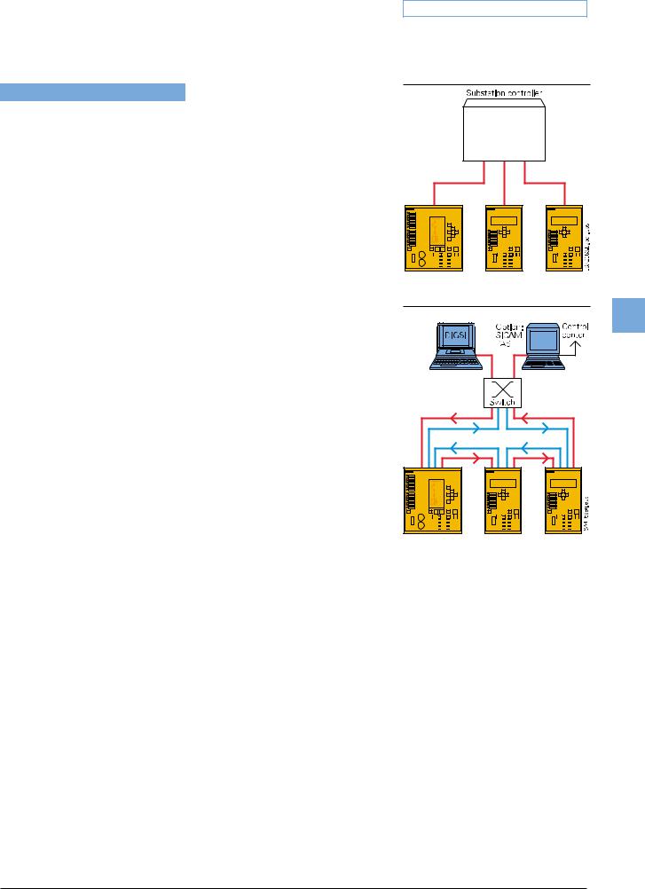
Fig. 5/87
IEC 60870-5-103: Radial fiber-optic connection
5
Fig. 5/88
Bus structure for station bus with Ethernet and IEC 61850, fiber-optic ring
1)For units in panel surface-mounting housings please refer to note on page 5/99.
Siemens SIP · 2008 |
5/85 |
5 Overcurrent Protection / 7SJ61
Communication
DNP 3.0 protocol
Power supply corporations use the serial DNP 3.0 (Distributed Network Protocol) for the station and network control levels. SIPROTEC units function as DNP slaves, supplying their information to a master system or receiving information from it.
System solutions for protection and station control
Together with the SICAM power automation system, SIPROTEC 4 can be used with PROFIBUS-FMS. Over the low-cost electrical RS485 bus, or interference-free via the optical double ring, the units exchange
information with the control system.
5
Units featuring IEC 60870-5-103 interfaces can be connected to SICAM in parallel via the RS485 bus or radially by fiber-optic link. Through this interface, the system is open for the connection of units of other manufacturers (see Fig. 5/87).
Because of the standardized interfaces, SIPROTEC units can also be integrated into systems of other manufacturers or in SIMATIC. Electrical RS485 or optical interfaces are available. The optimum physical data transfer medium can be chosen thanks to opto-electrical converters. Thus, the RS485 bus allows low-cost wiring in the cubicles and an interference-free optical connection to the master can be established.
For IEC 61850, an interoperable system solution is offered with SICAM PAS. Via the 100 Mbits/s Ethernet bus, the units are linked with PAS electrically or optically to the station PC. The interface is standardized, thus also enabling direct connection of units of other manufacturers to the Ethernet bus. With IEC 61850, however, the units can also be used in other manufacturers’ systems (see Fig. 5/88).
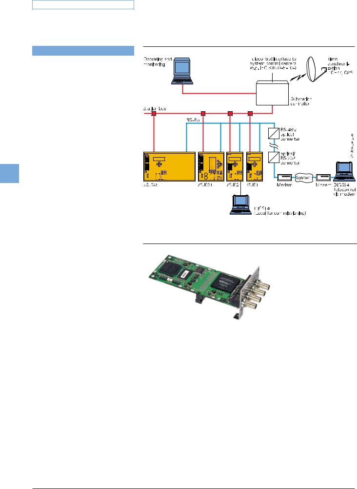
Fig. 5/89
System solution/communication
Fig. 5/90
Optical Ethernet communication module
for IEC 61850 with integrated Ethernet-switch
LSP2810.tif
5/86 |
Siemens SIP · 2008 |