

Курсовая работа по РЗА / Терминалы / каталоги / 7SJ61xx_Catalog_SIP-2008_en
.pdf5 Overcurrent Protection / 7SJ61
Typical connections
Connection of current and voltage transformers
Standard connection
For earthed networks, the earth current is obtained from the phase currents by the residual current circuit.
Fig. 5/91
Residual current
circuit
5
Fig. 5/92
Sensitive earth current detection
Siemens SIP · 2008 |
5/87 |
5 Overcurrent Protection / 7SJ61
Typical applications
Overview of connection types
Type of network |
Function |
Current connection |
(Low-resistance) earthed network |
Time-overcurrent protection |
Residual circuit, with 3 phase-current transformers |
|
phase/earth non-directional |
required, phase-balance neutral current transformer |
|
|
possible |
|
|
|
(Low-resistance) earthed networks |
Sensitive earth-fault protection |
Phase-balance neutral current |
|
|
transformers required |
|
|
|
Isolated or compensated networks |
Time-overcurrent protection |
Residual circuit, with 3 or 2 phase |
|
phases non-directional |
current transformers possible |
|
|
|
Isolated networks |
Sensitive earth-fault |
Phase-balance neutral current transformers |
|
protection |
required |
|
|
|
Compensated networks |
Sensitive earth-fault protection |
Phase-balance neutral current |
|
|
transformers required |
|
|
|
5
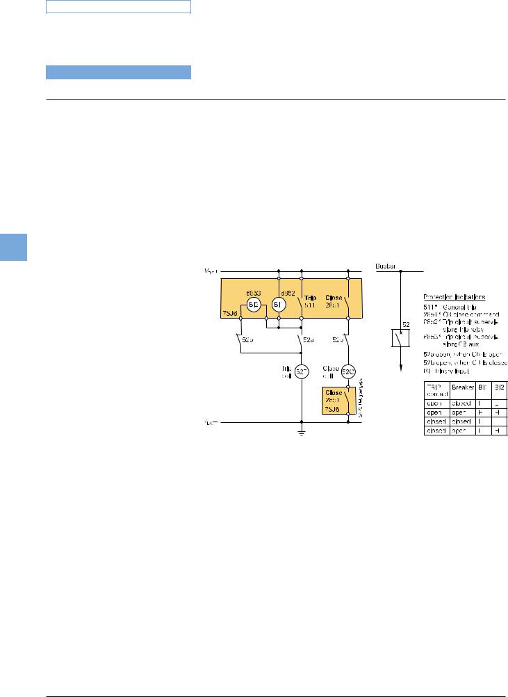
Trip circuit supervision (ANSI 74TC)
One or two binary inputs can be used for monitoring the circuit-breaker trip coil including its incoming cables. An alarm signal occurs whenever the circuit is interrupted.
Fig. 5/93 Trip circuit supervision with 2 binary inputs
5/88 |
Siemens SIP · 2008 |

Technical data |
|
|
|
|
|
|
|
|
|
|
|
|
|
|
|
|
|
|
|
General unit data |
|
|
|
|
|
|
|
|
|
Measuring circuits |
|
|
|
|
|
|
|
|
|
System frequency |
|
|
|
50 / 60 Hz (settable) |
|
||||
Current transformer |
|
|
|
|
|
|
|
|
|
Rated current Inom |
|
|
|
1 or 5 A (settable) |
|
||||
Option: sensitive earth-fault CT |
|
IEE < 1.6 A |
|
|
|||||
Power consumption |
|
|
|
|
|
|
|
|
|
at Inom = 1 A |
|
|
|
Approx. 0.05 VA per phase |
|||||
at Inom = 5 A |
|
|
|
Approx. 0.3 VA per phase |
|
||||
for sensitive earth-fault CT at 1 A |
Approx. 0.05 VA |
|
|||||||
Overload capability |
|
|
|
|
|
|
|
|
|
Thermal (effective) |
|
|
|
100 x Inom for 1 s |
|
||||
|
|
|
|
30 x Inom for 10 s |
|
||||
|
|
|
|
4 x Inom continuous |
|
||||
Dynamic (impulse current) |
|
250 x Inom (half cycle) |
|
||||||
Overload capability if equipped with |
|
|
|
|
|
|
|||
sensitive earth-fault CT |
|
|
|
|
|
|
|
|
|
Thermal (effective) |
|
|
|
300 A for 1 s |
|
|
|||
|
|
|
|
100 A for 10 s |
|
|
|||
|
|
|
|
15 A continuous |
|
||||
Dynamic (impulse current) |
|
750 A (half cycle) |
|
||||||
Auxiliary voltage (via integrated converter) |
|
|
|
|
|
||||
Rated auxiliary |
DC |
24/48 V |
60/125 V |
110/250 V |
|
||||
voltage Vaux |
AC |
|
|
|
|
|
115/230 V |
|
|
Permissible tolerance |
DC |
19–58 V |
48–150 V 88–330 V |
|
|||||
|
AC |
|
|
|
|
|
92–138 V |
184–265 V |
|
Ripple voltage, |
≤ 12 % |
|
|
|
|
|
|
||
peak-to-peak |
|
|
|
|
|
|
|
|
|
Power consumption |
|
|
|
|
|
|
|
|
|
Quiescent |
Approx. 3 W |
|
|
|
|
|
|||
Energized |
Approx. 7 W |
|
|
|
|
|
|||
Backup time during |
≥ 50 ms at V ≥ 110 V DC |
|
|||||||
loss/short-circuit of |
≥ 20 ms at V ≥ 24 V DC |
|
|||||||
auxiliary voltage |
≥ 200 ms at 115 V/230 V AC |
|
|||||||
Binary inputs/indication inputs |
|
|
|
|
|
|
|
||
Type |
|
7SJ610 |
|
7SJ611 |
7SJ612 |
||||
Number |
3 |
|
|
8 |
|
11 |
|
||
Voltage range |
|
24–250 V DC |
|
|
|
|
|
||
Pickup threshold |
|
Modifiable by plug-in jumpers |
|
||||||
Pickup threshold |
|
DC 19 V |
|
|
|
|
88 V |
||
For rated control voltage |
|
DC 24/48/60/110/125 V |
110/220/250 V |
||||||
Response time/drop-out |
|
Approx. 3.5 ms |
|
|
|||||
time |
|
|
|
|
|
|
|
|
|
Power consumption |
|
1.8 mA (independent of operating voltage) |
|||||||
energized |
|
|
|
|
|
|
|
|
|
|
|
|
|
|
|
|
|||
Binary outputs/command outputs |
|
|
|
|
|
|
|||
Type |
|
|
|
|
|
7SJ610 |
7SJ611 |
7SJ612 |
|
Number command/ |
|
|
|
|
|
4 |
|
8 |
6 |
indication relay |
|
|
|
|
|
|
|
|
|
Contacts per command/ |
|
|
|
|
|
1 NO / form A |
|
||
indication relay |
|
|
|
|
|
(2 contacts changeable to |
|||
|
|
|
|
|
|
NC/form B, |
|
||
|
|
|
|
|
|
via jumpers) |
|
||
Live status contact |
|
|
|
|
|
1 NO / NC (jumper) / form |
|||
|
|
|
|
|
|
A / B |
|
|
|
Switching capacity |
|
|
Make |
|
1000 W / VA |
|
|||
|
|
|
|
|
|
||||
|
|
|
Break |
|
30 W / VA / 40 W resistive / |
||||
|
|
|
|
|
|
25 W at L/R ≤ 50 ms |
|||
Switching voltage |
|
|
≤ 250 V DC |
|
|
||||
|
|
|
|
|
|
|
|
|
|
5 Overcurrent Protection / 7SJ61
Permissible current |
5 A continuous, |
|
|
30 A for 0.5 s making current, |
|
|
2000 switching cycles |
|
Electrical tests |
|
|
Specification |
|
|
Standards |
IEC 60255 |
|
|
ANSI C37.90, C37.90.1, C37.90.2, |
|
|
UL508 |
|
Insulation tests |
|
|
Standards |
IEC 60255-5; ANSI/IEEE C37.90.0 |
|
Voltage test (100 % test) |
2.5 kV (r.m.s. value), 50/60 Hz |
|
all circuits except for auxiliary |
|
|
voltage and RS485/RS232 and |
|
|
time synchronization |
|
|
Auxiliary voltage |
3.5 kV DC |
|
|
||
Communication ports |
500 V AC |
5 |
and time synchronization |
|
|
|
|
|
Impulse voltage test (type test) |
5 kV (peak value); 1.2/50 µs; 0.5 J |
|
all circuits, except communication |
3 positive and 3 negative impulses |
|
ports and time synchronization, |
at intervals of 5 s |
|
class III |
|
|
EMC tests for interference immunity; type tests
Standards
High-frequency test IEC 60255-22-1, class III
and VDE 0435 Part 303, class III
Electrostatic discharge IEC 60255-22-2 class IV and EN 61000-4-2, class IV
Irradiation with radio-frequency field, non-modulated
IEC 60255-22-3 (Report) class III
Irradiation with radio-frequency field, amplitude-modulated IEC 61000-4-3; class III
Irradiation with radio-frequency field, pulse-modulated
IEC 61000-4-3/ENV 50204; class III
Fast transient interference/burst IEC 60255-22-4 and IEC 61000-4-4, class IV
High-energy surge voltages (Surge)
IEC 61000-4-5; class III Auxiliary voltage
Binary inputs/outputs
Line-conducted HF, amplitude-modulated IEC 61000-4-6, class III
Power frequency magnetic field IEC 61000-4-8, class IV
IEC 60255-6
Oscillatory surge withstand capability
ANSI/IEEE C37.90.1
IEC 60255-6; IEC 60255-22 (product standard)
EN 50082-2 (generic specification) DIN 57435 Part 303
2.5 kV (peak value); 1 MHz; τ =15 ms;
400 surges per s; test duration 2 s
8 kV contact discharge;
15 kV air gap discharge;
both polarities; 150 pF; Ri = 330 Ω
10 V/m; 27 to 500 MHz
10 V/m, 80 to 1000 MHz; AM 80 %; 1 kHz
10 V/m, 900 MHz; repetition rate 200 Hz, on duration 50 %
4 kV; 5/50 ns; 5 kHz; burst length = 15 ms;
repetition rate 300 ms; both polarities; Ri = 50 Ω; test duration 1 min
From circuit to circuit: 2 kV; 12 Ω; 9 µF across contacts: 1 kV; 2 Ω ;18 µF
From circuit to circuit: 2 kV; 42 Ω; 0.5 µF across contacts: 1 kV; 42 Ω; 0.5 µF
10 V; 150 kHz to 80 MHz; AM 80 %; 1 kHz
30 A/m; 50 Hz, continuous
300 A/m; 50 Hz, 3 s
0.5 mT, 50 Hz
2.5 to 3 kV (peak value), 1 to 1.5 MHz damped wave; 50 surges per s; duration 2 s, Ri = 150 to 200 Ω
Siemens SIP · 2008 |
5/89 |

5 Overcurrent Protection / 7SJ61
Technical data
|
|
EMC tests for interference immunity; type tests (cont'd) |
||||
|
|
Fast transient surge withstand |
4 to 5 kV; 10/150 ns; 50 surges per s |
|||
|
|
capability ANSI/IEEE C37.90.1 |
both polarities; duration 2 s, Ri = 80 Ω |
|||
|
|
Radiated electromagnetic |
35 V/m; 25 to 1000 MHz; |
|||
|
|
interference |
amplitude and pulse-modulated |
|||
|
|
ANSI/IEEE C37.90.2 |
|
|||
|
|
Damped wave |
2.5 kV (peak value, polarity |
|||
|
|
IEC 60694 / IEC 61000-4-12 |
alternating) |
|||
|
|
|
|
|
|
100 kHz, 1 MHz, 10 and 50 MHz, |
|
|
|
|
|
|
Ri = 200 Ω |
|
|
EMC tests for interference emission; type tests |
||||
|
|
Standard |
EN 50081-* (generic specification) |
|||
|
|
Conducted interferences |
150 kHz to 30 MHz |
|||
|
|
only auxiliary voltage IEC/CISPR 22 |
Limit class B |
|||
|
|
Radio interference field strength |
30 to 1000 MHz |
|||
|
||||||
5 |
|
IEC/CISPR 11 |
Limit class B |
|||
|
Units with a detached operator |
|
||||
|
|
|
||||
|
|
panel must be installed in a metal |
|
|||
|
|
cubicle to maintain limit class B |
|
|||
|
|
|
|
|
|
|
|
|
Mechanical stress tests |
|
|||
|
|
Vibration, shock stress and seismic vibration |
||||
|
|
During operation |
|
|||
|
|
|
|
|
|
|
|
|
Standards |
IEC 60255-21 and IEC 60068-2 |
|||
|
|
Vibration |
Sinusoidal |
|||
|
|
IEC 60255-21-1, class 2 |
10 to 60 Hz; +/- 0.075 mm amplitude; |
|||
|
|
IEC 60068-2-6 |
60 to 150 Hz; 1 g acceleration |
|||
|
|
|
|
|
|
frequency sweep 1 octave/min |
|
|
|
|
|
|
20 cycles in 3 perpendicular axes |
|
|
|
|
|
|
|
|
|
Shock |
Semi-sinusoidal |
|||
|
|
IEC 60255-21-2, class 1 |
Acceleration 5 g, duration 11 ms; |
|||
|
|
IEC 60068-2-27 |
3 shocks in both directions of 3 axes |
|||
|
|
Seismic vibration |
Sinusoidal |
|||
|
|
IEC 60255-21-3, class 1 |
1 to 8 Hz: ± 3.5 mm amplitude |
|||
|
|
IEC 60068-3-3 |
(horizontal axis) |
|||
|
|
|
|
|
|
1 to 8 Hz: ± 1.5 mm amplitude |
|
|
|
|
|
|
(vertical axis) |
|
|
|
|
|
|
8 to 35 Hz: 1 g acceleration |
|
|
|
|
|
|
(horizontal axis) |
|
|
|
|
|
|
8 to 35 Hz: 0.5 g acceleration |
|
|
|
|
|
|
(vertical axis) |
|
|
|
|
|
|
Frequency sweep 1 octave/min |
|
|
|
|
|
|
1 cycle in 3 perpendicular axes |
|
|
During transportation |
|
|||
|
|
|
|
|
|
|
|
|
Standards |
IEC 60255-21 and IEC 60068-2 |
|||
|
|
|
|
|
|
|
|
|
Vibration |
Sinusoidal |
|||
|
|
IEC 60255-21-1, class 2 |
5 to 8 Hz: ± 7.5 mm amplitude; |
|||
|
|
IEC 60068-2-6 |
8 to 150 Hz; 2 g acceleration, |
|||
|
|
|
|
|
|
frequency sweep 1 octave/min |
|
|
|
|
|
|
20 cycles in 3 perpendicular axes |
|
|
Shock |
Semi-sinusoidal |
|||
|
|
IEC 60255-21-2, Class 1 |
Acceleration 15 g, duration 11 ms |
|||
|
|
IEC 60068-2-27 |
3 shocks in both directions of 3 axes |
|||
|
|
Continuous shock |
Semi-sinusoidal |
|||
|
|
IEC 60255-21-2, class 1 |
Acceleration 10 g, duration 16 ms |
|||
|
|
IEC 60068-2-29 |
1000 shocks in both directions |
|||
|
|
|
|
|
|
of 3 axes |
|
|
|
|
|
|
|
Climatic stress tests
Temperatures
Type-tested acc. to IEC 60068-2-1 |
-25 °C to +85 °C /-13 °F to +185 °F |
and -2, test Bd, for 16 h |
|
Temporarily permissible operating |
-20 °C to +70 °C /-4 °F to -158 °F |
temperature, tested for 96 h |
|
Recommended permanent operat- |
-5 °C to +55 °C /+25 °F to +131 °F |
ing temperature acc. to IEC 60255-6 |
|
(Legibility of display may be |
|
impaired above +55 °C /+131 °F) |
|
– Limiting temperature during |
-25 °C to +55 °C /-13 °F to +131 °F |
permanent storage |
|
– Limiting temperature during |
-25 °C to +70 °C /-13 °F to +158 °F |
transport |
|
Humidity |
|
Permissible humidity |
Annual average 75 % relative humid- |
It is recommended to arrange the |
ity; on 56 days a year up to 95 % rela- |
units in such a way that they are not |
tive humidity; condensation not |
exposed to direct sunlight or |
permissible! |
pronounced temperature changes |
|
that could cause condensation. |
|
Unit design |
|
Housing |
7XP20 |
Dimensions |
See dimension drawings, part 17 |
Weight |
|
Surface-mounting housing |
4.5 kg |
Flush-mounting housing |
4.0 kg |
Degree of protection |
|
acc. to EN 60529 |
|
Surface-mounting housing |
IP 51 |
Flush-mounting housing |
Front: IP 51, rear: IP 20; |
Operator safety |
IP 2x with cover |
Serial interfaces |
|
Operating interface (front of unit) |
|
Connection |
Non-isolated, RS232; front panel, |
|
9-pin subminiature connector |
Transmission rate |
Factory setting 115200 baud, |
|
min. 4800 baud, max. 115200 baud |
Service/modem interface (rear of unit)
Isolated interface for data transfer
Transmission rate
RS232/RS485
Connection
For flush-mounting housing/ surface-mounting housing with detached operator panel
For surface-mounting housing with two-tier terminal at the top/bottom part
Distance RS232
Distance RS485
Test voltage
Port C: DIGSI 4/modem/RTD-box
Factory setting 38400 baud,
min. 4800 baud, max. 115200 baud
9-pin subminiature connector, mounting location “C”
At the bottom part of the housing: shielded data cable
15 m /49.2 ft
Max. 1 km/3300 ft
500 V AC against earth
5/90 |
Siemens SIP · 2008 |

Technical data
System interface (rear of unit)
IEC 60870-5-103 protocol
Isolated interface for data transfer |
Port B |
to a control center |
|
Transmission rate |
Factory setting 9600 baud, |
|
min. 1200 baud, max. 115200 baud |
RS232/RS485 |
|
Connection |
|
For flush-mounting housing/ |
Mounting location “B” |
surface-mounting housing with |
|
detached operator panel |
|
For surface-mounting housing |
At the bottom part of the housing: |
with two-tier terminal on the |
shielded data cable |
top/bottom part |
|
Distance RS232 |
Max. 15 m/49 ft |
Distance RS485 |
Max. 1 km/3300 ft |
Test voltage |
500 V AC against earth |
Fiber optic |
|
Connection fiber-optic cable |
Integrated ST connector for fiber- |
|
optic connection |
For flush-mounting housing/ |
Mounting location “B” |
surface-mounting housing with |
|
detached operator panel |
|
For surface-mounting housing |
At the bottom part of the housing |
with two-tier terminal on the |
|
top/bottom part |
|
Optical wavelength |
820 nm |
Permissible path attenuation |
Max. 8 dB, for glass fiber 62.5/125 µm |
Distance |
Max. 1.5 km/0.9 miles |
IEC 60870-5-103 protocol, redundant
RS485
Connection
For flush-mounting housing/ surface-mounting housing with detached operator panel
For surface-mounting housing with two-tier terminal on the top/bottom part
Distance RS485 Test voltage
IEC 61850 protocol
Isolated interface for data transfer:
-to a control center
-with DIGSI
-between SIPROTEC 4 relays
Transmission rate
Ethernet, electrical
Connection
For flush-mounting housing/ surface-mounting housing with detached operator panel
Distance
Test voltage
Ethernet, optical
Connection
For flush-mounting housing/ surface-mounting housing with detached operator panel
Optical wavelength
Distance
Mounting location “B”
(not available)
Max. 1 km/3300 ft 500 V AC against earth
Port B, 100 Base T acc. to IEEE802.3
100 Mbit
Two RJ45 connectors mounting location "B"
Max. 20 m / 65.6 ft 500 V AC against earth
Integr. ST connector for FO connection Mounting location "B"
1300 nm
1.5 km/0.9 miles
5 Overcurrent Protection / 7SJ61
PROFIBUS-FMS/DP
Isolated interface for data transfer to a control center
Transmission rate
RS485
Connection
For flush-mounting housing/ surface-mounting housing with detached operator panel
For surface-mounting housing with two-tier terminal on the top/bottom part
Distance
Test voltage
Fiber optic
Connection fiber-optic cable For flush-mounting housing/
surface-mounting housing with detached operator panel
For surface-mounting housing with two-tier terminal on the top/bottom part
Optical wavelength Permissible path attenuation Distance
MODBUS RTU, ASCII, DNP 3.0
Port B
Up to 1.5 Mbaud
9-pin subminiature connector, mounting location “B”
At the bottom part of the housing: shielded data cable
1000 m/3300 ft ≤ 93.75 kbaud;
500 m/1500 ft ≤ 187.5 kbaud;
200 m/600 ft ≤ 1.5 Mbaud;
100 m/300 ft ≤ 12 Mbaud
500 V AC against earth
5
Integr. ST connector for FO connection Mounting location “B”
At the bottom part of the housing Important: Please refer to footnotes 1) and 2) on page 5/99
820 nm
Max. 8 dB, for glass fiber 62.5/125 µm
500 kB/s 1.6 km/0.99 miles
1500 kB/s 530 m/0.33 miles
Isolated interface for data transfer to a control center
Transmission rate
RS485
Connection
For flush-mounting housing/ surface-mounting housing with detached operator panel
For surface-mounting housing with two-tier terminal at the top/bottom part
Distance
Test voltage
Fiber-optic
Connection fiber-optic cable
For flush-mounting housing/ surface-mounting housing with detached operator panel
For surface-mounting housing with two-tier terminal at the top/bottom part
Optical wavelength
Permissible path attenuaion Distance
Port B
Up to 19200 baud
9-pin subminiature connector, mounting location “B”
At bottom part of the housing: shielded data cable
Max. 1 km/3300 ft max. 32 units recommended
500 V AC against earth
Integrated ST connector for fiber-optic connection
Mounting location “B”
At the bottom part of the housing Important: Please refer to footnotes 1) and 2) on page 5/99
820 nm
Max. 8 dB, for glass fiber 62.5/125 µm Max. 1.5 km/0.9 miles
Siemens SIP · 2008 |
5/91 |

5 Overcurrent Protection / 7SJ61
Technical data
|
|
Time synchronization DCF77/IRIG-B signal (Format IRIG-B000) |
|
|
|
Connection |
9-pin subminiature connector |
|
|
|
(SUB-D) |
|
|
|
(terminal with surface-mounting |
|
|
|
housing) |
|
|
Voltage levels |
5 V, 12 V or 24 V (optional) |
|
|
Functions |
|
|
|
Definite-time overcurrent protection (ANSI 50, 50N) |
|
|
|
Operating mode phase protection |
3-phase (standard) or 2-phase |
|
|
(ANSI 50) |
(L1 and L3) |
|
|
Number of elements (stages) |
I>, I>>, I>>> (phases) |
|
|
|
IE>, IE>>, IE>>> (earth) |
|
|
Setting ranges |
|
|
|
Pickup phase elements |
0.5 to 175 A or ∞1) (in steps of 0.01 A) |
|
|
Pickup earth elements |
0.25 to 175 A or ∞1) (in steps of 0.01 A) |
|
|||
5 |
|
Delay times T |
0 to 60 s or ∞ (in steps of 0.01 s) |
|
Dropout delay time TDO |
0 to 60 s (in steps of 0.01 s) |
|
|
|
Times |
|
|
|
Pickup times (without inrush |
|
|
|
restraint, with inrush restraint |
|
|
|
+ 10 ms) |
|
|
|
With twice the setting value |
Approx. 30 ms |
|
|
With five times the setting value |
Approx. 20 ms |
|
|
Dropout times |
Approx. 40 ms |
|
|
Dropout ratio |
Approx. 0.95 for I/Inom ≥ 0.3 |
|
|
Tolerances |
2 % of setting value or 50 mA1) |
|
|
Pickup |
|
|
|
Delay times T, TDO |
1 % or 10 ms |
Inverse-time overcurrent protection (ANSI 51, 51N)
Operating mode phase protection (ANSI 51)
Setting ranges
Pickup phase element IP Pickup earth element IEP Time multiplier T
(IEC characteristics) Time multiplier D (ANSI characteristics)
Trip characteristics
IEC
ANSI
User-defined characteristic
Dropout setting
Without disk emulation
With disk emulation
Tolerances
Pickup/dropout thresholds Ip, IEp Pickup time for 2 ≤ I/Ip ≤ 20
Dropout ratio for 0.05 ≤ I/Ip ≤ 0.9
3-phase (standard) or 2-phase
(L1 and L3)
0.5 to 20 A or ∞ 1) (in steps of 0.01 A) 0.25 to 20 A or ∞ 1) (in steps of 0.01 A)
0.05 to 3.2 s or ∞ (in steps of 0.01 s)
0.05 to 15 s or ∞ (in steps of 0.01 s)
Normal inverse, very inverse, extremely inverse, long inverse Inverse, short inverse, long inverse moderately inverse, very inverse, extremely inverse, definite inverse
Defined by a maximum of 20 value pairs of current and time delay
Approx. 1.05 · setting value Ip for Ip/Inom ≥ 0.3, corresponds to approx. 0.95 · pickup threshold
Approx. 0.90 · setting value Ip
2 % of setting value or 50 mA1)
5 % of reference (calculated) value
+2 % current tolerance, respectively
30 ms
5 % of reference (calculated) value
+2 % current tolerance, respectively
30 ms
1) For Inom = 1 A, all limits divided by 5.
Inrush blocking
Influenced functions |
Time-overcurrent elements, I>, IE>, |
|
Ip, IEp |
Lower function limit phases |
At least one phase current |
|
(50 Hz and 100 Hz) ≥ 125 mA 1) |
Lower function limit earth |
Earth current (50 Hz and 100 Hz) |
|
≥ 125 mA 1) |
Upper function limit (setting range) 1.5 to 125 A 1) (in steps of 0.01 A)
Setting range I2f /I |
10 to 45 % (in steps of 1 %) |
Crossblock (IL1, IL2, IL3) |
ON/OFF |
Dynamic setting change |
|
Controllable function |
Pickup, tripping time |
Start criteria |
Current criteria, |
|
CB position via aux. contacts, |
|
binary input, |
|
auto-reclosure ready |
Time control |
3 timers |
Current criteria |
Current threshold |
|
(reset on dropping below threshold; |
|
monitoring with timer) |
(Sensitive) earth-fault detection (ANSI 50 Ns, 51Ns)
Earth-fault pickup for all types of earth faults
Definite-time characteristic (ANSI 50Ns)
Setting ranges
Pickup threshold IEE>, IEE>> For sensitive input
For normal input
Delay times T for IEE>, IEE>> Dropout delay time TDO
Times
Pickup times
Dropout ratio
Tolerances
Pickup threshold IEE>, IEE>> Delay times
0.001 to 1.5 A (in steps of 0.001 A) 0.25 to 175 A1) (in steps of 0.01 A) 0 to 320 s or ∞ (in steps of 0.01 s) 0 to 60 s (in steps of 0.01 s)
Approx. 50 ms
Approx. 0.95
2 % of setting value or 1 mA
1 % of setting value or 20 ms
Earth-fault pickup for all types of earth faults
Inverse-time characteristic (ANSI 51Ns)
User-defined characteristic |
Defined by a maximum of 20 pairs of |
|
current and delay time values |
Setting ranges |
|
Pickup threshold IEEp |
|
For sensitive input |
0.001 A to 1.4 A (in steps of 0.001 A) |
For normal input |
0.25 to 20 A1) (in steps of 0.01 A) |
User defined |
0.1 to 4 s or ∞ (in steps of 0.01 s) |
Time multiplier T |
|
|
|
Times |
|
Pickup times |
Approx. 50 ms |
Pickup threshold |
Approx. 1.1 · IEEp |
Dropout ratio |
Approx. 1.05 · IEEp |
Tolerances |
|
Pickup threshold |
|
For sensitive input |
2 % of setting value or 1 mA |
For normal input |
2 % of setting value or 50 mA1) |
Dropout times in linear range |
7 % of reference value for 2 ≤ I/IEEp |
|
≤ 20 + 2 % current tolerance, or 70 ms |
Logarithmic inverse |
Refer to the manual |
Logarithmic inverse with knee point |
Refer to the manual |
|
|
5/92 |
Siemens SIP · 2008 |

Technical data
High-impedance restricted earth-fault protection (ANSI 87N) / single-phase overcurrent protection
Setting ranges |
|
Pickup thresholds I>, I>> |
0.003 to 1.5 A or ∞ (in steps of 0.001 A) |
For sensitive input |
|
For normal input |
0.25 to 175 A1) or ∞ (in steps of 0.01 A) |
Delay times TI>, TI>> |
0 to 60 s or ∞ (in steps of 0.01 s) |
Times |
|
Pickup times |
|
Minimum |
Approx. 20 ms |
Typical |
Approx. 30 ms |
Dropout times |
Approx. 30 ms |
Dropout ratio |
Approx. 0.95 for I/Inom ≥ 0.5 |
Tolerances |
|
Pickup thresholds |
3 % of setting value or |
|
1 % rated current at Inom = 1 or 5 A; |
|
5 % of setting value or |
|
3 % rated current at Inom = 0.1 A |
Delay times |
1 % of setting value or 10 ms |
|
|
Intermittent earth-fault protection
Setting ranges |
|
Pickup threshold |
|
For IE |
IIE> |
For 3I0 |
IIE> |
For IEE |
IIE> |
Pickup prolon- |
TV |
gation time |
|
Earth-fault accu- |
Tsum |
mulation time |
|
Reset time for |
Tres |
accumulation |
|
Number of pickups for |
|
intermittent earth fault |
|
Times
Pickup times
Current = 1.25 · pickup value Current ≥ 2 · pickup value
Dropout time
Tolerances
Pickup threshold IIE>
Times TV, Tsum, Tres
0.25 to 175 A1) (in steps of 0.01 A) 0.25 to 175 A1) (in steps of 0.01 A) 0.005 to 1.5 A (in steps of 0.001 A)
0 to 10 s (in steps of 0.01 s)
0 to 100 s (in steps of 0.01 s)
1 to 600 s (in steps of 1 s)
2 to 10 (in steps of 1)
Approx. 30 ms
Approx. 22 ms
Approx. 22 ms
3 % of setting value, or 50 mA1)
1 % of setting value or 10 ms
Thermal overload protection (ANSI 49)
Setting ranges
Factor k
Time constant
Warning overtemperature
Θalarm/Θtrip
Current warning stage Ialarm
Extension factor when stopped kτ factor
Rated overtemperature (for Inom)
0.1 to 4 (in steps of 0.01)
1 to 999.9 min (in steps of 0.1 min)
50 to 100 % with reference
to the tripping overtemperature (in steps of 1 %)
0.5 to 20 A (in steps of 0.01 A)
1 to 10 with reference to the time constant with the machine running (in steps of 0.1)
40 to 200 °C (in steps of 1 °C)
1) For Inom = 1 A, all limits divided by 5.
5 Overcurrent Protection / 7SJ61
Tripping characteristic
For (I/k · Inom) ≤ 8
Dropout ratios
Θ/ΘTrip Θ/ΘAlarm
I/IAlarm
Tolerances
With reference to k · Inom With reference to tripping time
Auto-reclosure (ANSI 79)
t = τ th ln(I /k Inom)2 −(Ipre /k Inom)2 (I / k Inom)2 −1
t = Tripping time
τth = Temperature rise time constant
I = Load current Ipre = Preload current
k = Setting factor acc. to VDE 0435
Part 3011 and IEC 60255-8 Inom = Rated (nominal) current of the
protection relay
Drops out with ΘAlarm Approx. 0.99 Approx. 0.97
5
Class 5 acc. to IEC 60255-8
5 % +/- 2 s acc. to IEC 60255-8
Number of reclosures |
0 to 9 |
|
Shot 1 to 4 individually adjustable |
Program for phase fault |
|
Start-up by |
Time-overcurrent elements, negative |
|
sequence, binary input |
|
|
Program for earth fault |
|
Start-up by |
Time-overcurrent elements, sensitive |
|
earth-fault protection, binary input |
Blocking of ARC |
Pickup of protection functions, |
|
three-phase fault detected by a protec- |
|
tive element, binary input, |
|
last TRIP command after the reclosing |
|
cycle is complete (unsuccessful |
|
reclosing), |
|
TRIP command by the breaker failure |
|
protection (50BF), |
|
opening the CB without ARC |
|
initiation, |
|
external CLOSE command |
Setting ranges |
|
Dead time |
0.01 to 320 s (in steps of 0.01 s) |
(separate for phase and earth |
|
and individual for shots 1 to 4) |
|
Blocking duration for manual- |
0.5 s to 320 s or 0 (in steps of 0.01 s) |
CLOSE detection |
|
Blocking duration after |
0.5 s to 320 s (in steps of 0.01 s) |
reclosure |
|
Blocking duration after |
0.01 to 320 s (in steps of 0.01 s) |
dynamic blocking |
|
Start-signal monitoring time |
0.01 to 320 s or ∞ (in steps of 0.01 s) |
Circuit-breaker supervision |
0.1 to 320 s (in steps of 0.01 s) |
time |
|
Max. delay of dead-time start |
0 to 1800 s or ∞ (in steps of 0.1 s) |
Maximum dead time extension |
0.5 to 320 s or ∞(in steps of 0.01 s) |
Action time |
0.01 to 320 s or ∞ (in steps of 0.01 s) |
The delay times of the following protection function can be altered individually by the ARC for shots 1 to 4
(setting value T = T, non-delayed T = 0, blocking T = ∞): I>>>, I>>, I>, Ip,
IE>>>, IE>>, IE>, IEp
Siemens SIP · 2008 |
5/93 |

5 Overcurrent Protection / 7SJ61
Technical data
|
|
Auto-reclosure (ANSI 79) (cont'd) |
|
|
|
Additional functions |
Lockout (final trip), |
|
|
|
delay of dead-time start via binary |
|
|
|
input (monitored), |
|
|
|
dead-time extension via binary input |
|
|
|
(monitored), |
|
|
|
co-ordination with other protection |
|
|
|
relays, |
|
|
|
circuit-breaker monitoring, |
|
|
|
evaluation of the CB contacts |
|
|
Breaker failure protection (ANSI 50 BF) |
|
|
|
Setting ranges |
0.2 to 5 A1) (in steps of 0.01 A) |
|
|
Pickup thresholds |
|
|
|
Delay time |
0.06 to 60 s or ∞ (in steps of 0.01 s) |
|
|
Times |
|
|
|
Pickup times |
|
|
|
||
|
|
with internal start |
is contained in the delay time |
5 |
|
with external start |
is contained in the delay time |
|
Dropout times |
Approx. 25 ms |
|
|
|
||
|
|
Tolerances |
2 % of setting value (50 mA)1) |
|
|
Pickup value |
|
|
|
Delay time |
1 % or 20 ms |
|
|
Flexible protection functions (ANSI 47, 50, 50N) |
|
|
|
Operating modes/measuring |
|
|
|
quantities |
|
|
|
3-phase |
I, I1, I2, I2/I1, 3I0 |
|
|
1-phase |
I, IE, IE sens. |
|
|
Without fixed phase relation |
Binary input |
|
|
Pickup when |
Exceeding or falling below threshold |
|
|
|
value |
|
|
Setting ranges |
0.15 to 200 A1) (in steps of 0.01 A) |
|
|
Current I, I1, I2, 3I0, IE |
|
|
|
Current ratio I2 / I1 |
15 to 100 % (in steps of 1 %) |
|
|
Sensitive earth current IE sens. |
0.001 to 1.5 A (in steps of 0.001 A) |
|
|
Dropout ratio >- stage |
1.01 to 3 (in steps of 0.01) |
|
|
Dropout ratio <- stage |
0.7 to 0.99 (in steps of 0.01) |
|
|
Pickup delay time |
0 to 60 s (in steps of 0.01 s) |
|
|
Trip delay time |
0 to 3600 s (in steps of 0.01 s) |
|
|
Dropout delay time |
0 to 60 s (in steps of 0.01 s) |
|
|
Times |
|
|
|
Pickup times, phase quantities |
|
|
|
With 2 times the setting value |
Approx. 30 ms |
|
|
With 10 times the setting value |
Approx. 20 ms |
|
|
Pickup times, symmetrical |
|
|
|
components |
|
|
|
With 2 times the setting value |
Approx. 40 ms |
|
|
With 10 times the setting value |
Approx. 30 ms |
|
|
Binary input |
Approx. 20 ms |
|
|
Dropout times |
|
|
|
Phase quantities |
< 20 ms |
|
|
Symmetrical components |
< 30 ms |
|
|
Binary input |
< 10 ms |
|
|
Tolerances |
|
|
|
Pickup threshold |
1 % of setting value or 50 mA1) |
|
|
Phase quantities |
|
|
|
Symmetrical components |
2 % of setting value or 100 mA1) |
|
|
Times |
1 % of setting value or 10 ms |
|
|
Negative-sequence current detection (ANSI 46) |
|
|
|
Definite-time characteristic (ANSI 46-1 and 46-2) |
|
|
|
Setting ranges |
|
|
|
Pickup current I2>, I2>> |
0.5 to 15 A or ∞ (in steps of 0.01 A) |
|
|
Delay times |
0 to 60 s or ∞ (in steps of 0.01 s) |
|
|
Dropout delay time TDO |
0 to 60 s (in steps of 0.01 s) |
|
|
Functional limit |
All phase currents ≤ 50 A1) |
|
|
|
|
Times |
|
Pickup times |
Approx. 35 ms |
Dropout times |
Approx. 35 ms |
Dropout ratio |
Approx. 0.95 for I2 /Inom > 0.3 |
Tolerances |
3 % of the setting value or 50 mA1) |
Pickup thresholds |
|
Delay times |
1 % or 10 ms |
Inverse-time characteristic (ANSI 46-TOC)
Setting ranges |
0.5 to 10 A1) (in steps of 0.01 A) |
Pickup current |
|
Time multiplier T |
0.05 to 3.2 s or ∞ (in steps of 0.01 s) |
(IEC characteristics) |
0.5 to 15 s or ∞ (in steps of 0.01 s) |
Time multiplier D |
|
(ANSI characteristics) |
|
Functional limit |
All phase currents ≤ 50 A1) |
Trip characteristics |
|
IEC |
Normal inverse, very inverse, |
|
extremely inverse |
ANSI |
Inverse, moderately inverse, |
|
very inverse, extremely inverse |
Pickup threshold |
Approx. 1.1 · I2p setting value |
Dropout |
|
IEC and ANSI |
Approx. 1.05 · I2p setting value, |
(without disk emulation) |
which is approx. 0.95 · pickup threshold |
ANSI with disk emulation |
Approx. 0.90 · I2p setting value |
Tolerances |
3 % of the setting value or 50 mA1) |
Pickup threshold |
|
Time for 2 ≤ M ≤ 20 |
5 % of setpoint (calculated) |
|
+2 % current tolerance, at least 30 ms |
Starting time monitoring for motors (ANSI 48)
Setting ranges |
2.5 to 80 A1) (in steps of 0.01) |
||||
Motor starting current ISTARTUP |
|||||
Pickup threshold IMOTOR START |
2 to 50 A1) (in steps of 0.01) |
||||
Permissible starting |
1 to 180 s (in steps of 0.1 s) |
||||
time TSTARTUP, cold motor |
|
|
|
|
|
Permissible starting |
0.5 to 180 s (in steps of 0.1 s) |
||||
time TSTARTUP, warm motor |
|
|
|
|
|
Temperature threshold cold motor |
0 to 80 % (in steps of 1 %) |
||||
Permissible blocked rotor |
0.5 to 120 s or ∞ (in steps of 0.1 s) |
||||
time TLOCKED-ROTOR |
|
|
|
|
|
Tripping time characteristic |
|
ISTARTUP |
|
2 |
|
|
|||||
For I > IMOTOR START |
t = |
|
|
TSTARTUP |
|
I |
|||||
|
|
|
|
||
|
ISTARTUP = Rated motor starting |
||||
|
|
current |
|||
|
I |
= Actual current flowing |
|||
|
TSTARTUP = Tripping time for rated |
||||
|
|
motor starting current |
|||
|
t |
= Tripping time in seconds |
|||
Dropout ratio IMOTOR START |
Approx. 0.95 |
|
|
||
Tolerances |
2 % of setting value or 50 mA1) |
||||
Pickup threshold |
|||||
Delay time |
5 % or 30 ms |
|
|
||
Load jam protection for motors (ANSI 51M)
Setting ranges |
|
Current threshold for |
0.25 to 60 A1) (in steps of 0.01 A) |
alarm and trip |
|
Delay times |
0 to 600 s (in steps of 0.01 s) |
Blocking duration after |
0 to 600 s (in steps of 0.01 s) |
close signal detection |
|
Tolerances |
2 % of setting value or 50 mA1) |
Pickup threshold |
|
Delay time |
1 % of setting value or 10 ms |
1) At Inom = 1 A, all limits divided by 5.
5/94 |
Siemens SIP · 2008 |

Technical data
Restart inhibit for motors (ANSI 66)
Setting ranges
Motor starting current relative |
1.1 to 10 (in steps of 0.1) |
|||
to rated motor current |
|
|
|
|
IMOTOR START/IMotor Nom |
1 to 6 A1) (in steps of 0.01 A) |
|||
Rated motor current IMotor Nom |
||||
Max. permissible starting time |
1 to 320 s (in steps of 1 s) |
|||
TStart Max |
|
|
|
|
Equilibrium time TEqual |
0 min to 320 min (in steps of 0.1 min) |
|||
Minimum inhibit time |
0.2 min to 120 min (in steps of 0.1 min) |
|||
TMIN. INHIBIT TIME |
|
|
|
|
Max. permissible number of |
1 to 4 (in steps of 1) |
|||
warm starts |
|
|
|
|
Difference between cold and |
1 to 2 (in steps of 1) |
|||
warm starts |
|
|
|
|
Extension k-factor for cooling |
0.2 to 100 (in steps of 0.1) |
|||
simulations of rotor at zero speed |
|
|
|
|
kτ at STOP |
|
|
|
|
Extension factor for cooling time |
0.2 to 100 (in steps of 0.1) |
|||
constant with motor running |
|
|
|
|
kτ RUNNING |
|
|
|
|
Restarting limit |
|
|
nc −1 |
|
|
Θ restart |
= Θ rot max perm |
|
|
|
nc |
|||
|
|
|
||
|
Θrestart |
= Temperature limit below |
||
|
|
which restarting is possi- |
||
|
|
ble |
||
|
Θrot max perm = Maximum permissible |
|||
|
|
rotor overtemperature |
||
|
|
(= 100 % in operational |
||
|
|
measured value |
||
|
|
Θrot/Θrot trip) |
||
|
nc |
= Number of permissible |
||
|
|
start-ups from cold state |
||
Undercurrent monitoring (ANSI 37) |
|
|
|
|
Signal from the operational |
Predefined with programmable logic |
|||
measured values |
|
|
|
|
Temperature monitoring box (ANSI 38) |
|
|
|
|
Temperature detectors |
|
|
|
|
Connectable boxes |
1 or 2 |
|
|
|
Number of temperature |
Max. 6 |
|
|
|
detectors per box |
|
|
|
|
Type of measuring |
Pt 100 Ω or Ni 100 Ω or Ni 120 Ω |
|||
Mounting identification |
“Oil” or “Environment” or “Stator” or |
|||
|
“Bearing” or “Other” |
|||
Thresholds for indications |
|
|
|
|
For each measuring detector |
|
|
|
|
Stage 1 |
-50 °C to 250 °C (in steps of 1 °C) |
|||
|
-58 °F to 482 °F (in steps of 1 °F) |
|||
|
or ∞ (no indication) |
|||
Stage 2 |
-50 °C to 250 °C (in steps of 1 °C) |
|||
|
-58 °F to 482 °F (in steps of 1 °F) |
|||
|
or ∞ (no indication) |
|||
1) At rated frequency.
5 Overcurrent Protection / 7SJ61
Additional functions |
|
|
|
Operational measured values |
|
|
|
Currents |
In A (kA) primary, in A secondary |
|
|
IL1, IL2, IL3 |
or in % Inom |
|
|
Positive-sequence component I1 |
|
|
|
Negative-sequence component I2 |
|
|
|
IE or 3I0 |
|
|
|
Range |
10 to 200 % Inom |
|
|
Tolerance1) |
1 % of measured value or 0.5 % Inom |
|
|
Temperature overload protection |
In % |
|
|
Θ/ΘTrip |
|
|
|
Range |
0 to 400 % |
|
|
Tolerance1) |
5 % class accuracy per IEC 60255-8 |
|
|
Temperature restart inhibit |
In % |
|
|
ΘL/ΘL Trip |
|
|
|
Range |
0 to 400 % |
|
|
Tolerance1) |
5 % class accuracy per IEC 60255-8 |
5 |
|
Restart threshold ΘRestart/ΘL Trip |
In % |
||
|
|||
Reclose time TReclose |
In min |
|
|
Current of sensitive ground fault |
In A (kA) primary and in mA |
|
|
detection IEE |
secondary |
|
|
Range |
0 mA to 1600 mA |
|
|
Tolerance1) |
2 % of measured value or 1 mA |
|
|
RTD-box |
See section "Temperature monitoring |
|
|
|
box" |
|
|
Long-term averages |
|
|
|
Time window |
5, 15, 30 or 60 minuets |
|
|
Frequency of updates |
Adjustable |
|
|
Long-term averages |
|
|
|
of currents |
IL1dmd, IL2dmd, IL3dmd, I1dmd in A (kA) |
|
|
Max. / Min. report |
|
|
|
Report of measured values |
With date and time |
|
|
Reset, automatic |
Time of day adjustable (in minutes, |
|
|
|
0 to 1439 min) |
|
|
|
Time frame and starting time adjust- |
|
|
|
able (in days, 1 to 365 days, and ∞) |
|
|
Reset, manual |
Using binary input, |
|
|
|
using keypad, |
|
|
|
via communication |
|
|
Min./Max. values for current |
IL1, IL2, IL3 |
|
|
|
I1 (positive-sequence component) |
|
|
Min./Max. values for overload pro- |
Θ/ΘTrip |
|
|
tection |
|
|
|
Min./Max. values for mean values |
IL1dmd, IL2dmd, IL3dmd |
|
|
|
I1 (positive-sequence component) |
|
|
Local measured values monitoring |
|
|
|
Current asymmetry |
Imax/Imin > balance factor, |
|
|
|
for I>Ibalance limit |
|
|
Current phase sequence |
Clockwise (ABC) / counter-clockwise |
|
|
|
(ACB) |
|
|
Limit value monitoring |
Predefined limit values, user-defined |
|
|
|
expansions via CFC |
|
|
Fault recording |
|
|
|
Recording of indications of the last |
|
|
|
8 power system faults |
|
|
|
Recording of indications of the last |
|
|
|
3 power system ground faults |
|
|
Siemens SIP · 2008 |
5/95 |

5 Overcurrent Protection / 7SJ61
Technical data
Time stamping
|
|
Resolution for event log |
1 ms |
|
|
|
(operational annunciations) |
|
|
|
|
Resolution for trip log |
1 ms |
|
|
|
(fault annunciations) |
|
|
|
|
|
|
|
|
|
Maximum time deviation |
0.01 % |
|
|
|
(internal clock) |
|
|
|
|
Battery |
Lithium battery 3 V/1 Ah, |
|
|
|
|
type CR 1/2 AA, message "Battery |
|
|
|
|
Fault" for insufficient battery charge |
|
|
|
Oscillographic fault recording |
|
|
|
|
Maximum 8 fault records saved, |
|
|
|
|
memory maintained by buffer bat- |
|
|
|
|
tery in case of loss of power supply |
|
|
|
|
Recording time |
Total 20 s |
|
|
|
|||
|
|
|
Pre-trigger and post-fault recording |
|
5 |
|
|
and memory time adjustable |
|
|
Sampling rate for 50 Hz |
1 sample/1.25 ms (16 samples/cycle) |
||
|
|
|||
|
|
Sampling rate for 60 Hz |
1 sample/1.04 ms (16 samples/cycle) |
|
|
|
Statistics |
|
|
|
|
Saved number of trips |
Up to 9 digits |
|
|
|
|
|
|
|
|
Number of automatic reclosing |
Up to 9 digits |
|
|
|
commands (segregated according |
|
|
|
|
to 1st and ≥ 2nd cycle) |
|
|
|
|
Circuit-breaker wear |
|
|
|
|
Methods |
• ΣIx with x = 1 .. 3 |
|
|
|
|
• 2-point method |
|
|
|
|
(remaining service life) |
|
|
|
|
• Σi2t |
|
|
|
Operation |
Phase-selective accumulation of mea- |
|
|
|
|
sured values on TRIP command, up to |
|
|
|
|
8 digits, phase-selective limit values, |
|
|
|
|
monitoring indication |
|
|
|
Motor statistics |
|
|
|
|
Total number of motor start-ups |
0 to 9999 |
(resolution 1) |
|
|
Total operating time |
0 to 99999 h |
(resolution 1 h) |
|
|
Total down-time |
0 to 99999 h |
(resolution 1 h) |
|
|
Ratio operating time/down-time |
0 to 100 % |
(resolution 0.1 %) |
|
|
Motor start-up data: |
of the last 5 start-ups |
|
|
|
– start-up time |
0.30 s to 9999.99 s |
(resolution 10 ms) |
|
|
– start-up current (primary) |
0 A to 1000 kA |
(resolution 1 A) |
|
|
Operating hours counter |
|
|
|
|
Display range |
Up to 7 digits |
|
|
|
|
|
|
|
|
Criterion |
Overshoot of an adjustable current |
|
|
|
|
threshold (BkrClosed IMIN) |
|
|
|
Trip circuit monitoring |
|
|
|
|
With one or two binary inputs |
|
|
|
|
Commissioning aids |
|
|
|
|
Phase rotation field check, |
|
|
|
|
operational measured values, |
|
|
|
|
circuit-breaker/switching device |
|
|
|
|
test, |
|
|
|
|
creation of a test measurement |
|
|
|
|
report |
|
|
|
|
Clock |
|
|
|
|
Time synchronization |
DCF77/IRIG-B signal |
|
|
|
|
(telegram format IRIG-B000), |
|
|
|
|
binary input, |
|
|
|
|
communication |
|
|
|
|
|
|
Setting group switchover of the function parameters
Number of available setting groups |
4 (parameter group A, B, C and D) |
Switchover performed |
Via keypad, DIGSI, system (SCADA) |
|
interface or binary input |
Control |
|
Number of switching units |
Depends on the binary inputs and |
|
outputs |
Interlocking |
Programmable |
Circuit-breaker signals |
Feedback, close, open, intermediate |
|
position |
Control commands |
Single command / double command |
|
1, 1 plus 1 common or 2 trip contacts |
Programmable controller |
CFC logic, graphic input tool |
Local control |
Control via menu, |
|
assignment of a function key |
Remote control |
Via communication interfaces, |
|
using a substation automation and |
|
control system |
|
(e.g. SICAM), |
|
DIGSI 4 (e.g. via modem) |
CE conformity |
|
This product is in conformity with the Directives of the European Communities on the harmonization of the laws of the Member States relating to electromagnetic compatibility (EMC Council Directive 89/336/EEC) and electrical equipment designed for use within certain voltage limits (Council Directive 73/23/EEC).
This unit conforms to the international standard IEC 60255, and the German standard DIN 57435/Part 303 (corresponding to VDE 0435/Part 303).
Further applicable standards: ANSI/IEEE C37.90.0 and C37.90.1.
The unit conforms to the international standard IEC 60255, and the German standard DIN 57435/Part 303 (corresponding to VDE 0435/Part 303).
This conformity is the result of a test that was performed by Siemens AG in accordance with Article 10 of the Council Directive complying with the generic standards EN 50081-2 and EN 50082-2 for the EMC Directive and standard EN 60255-6 for the “low-voltage Directive”.
5/96 |
Siemens SIP · 2008 |