

Курсовая работа по РЗА / Терминалы / каталоги / 7SJ61xx_Catalog_SIP-2008_en
.pdf5 Overcurrent Protection / 7SJ61
|
|
|
|
Selection and ordering data |
Description |
Order No. |
|
|
7SJ61 multifunction protection relay |
7SJ61 – – |
|
Housing, binary inputs (BI) and outputs (BO) |
0 |
|
|
|
|
|
|
|
|
|
|
|
|
||
Housing 1/3 19”, 3 BI, 4 BO, 1 live status contact |
|
|
|
|
|
|
|
Housing 1/3 19”, 8 BI, 8 BO, 1 live status contact |
1 |
|
|
|
|
|
|
Housing 1/3 19”, 11 BI, 6 BO, 1 live status contact |
2 |
|
|
|
|
|
|
Measuring inputs ( 4 x I) |
|
|
|
|
|
|
|
Iph = 1 A1), Ie = 1 A1) (min. = 0.05 A) |
1 |
|
|
|
|
|
|
Position 15 only with A |
|
|
|
|
|
||
Iph = 1 A1), Ie = sensitive (min. = 0.001 A) |
2 |
|
|
|
|
|
|
Position 15 only with B |
|
|
|
|
|
||
Iph = 5 A1), Ie = 5 A1) (min. = 0.25 A) |
5 |
|
|
|
|
|
|
Position 15 only with A |
|
|
|
|
|
||
Iph = 5 A1), Ie = sensitive (min. = 0.001 A) |
6 |
|
|
|
|
|
|
Position 15 only with B |
|
|
|
|
|
||
Iph = 5 A1), Ie = 1 A1) (min. = 0.05 A) |
7 |
|
|
|
|
|
|
Position 15 only with A |
|
|
|
|
|
||
Rated auxiliary voltage (power supply, indication voltage) |
|
|
|
|
|
|
|
24 to 48 V DC, threshold binary input 19 DC3) |
2 |
|
|
|
|
||
60 to 125 V DC2), threshold binary input 19 DC3) |
4 |
|
|
|
|
||
110 to 250 V DC2), 115 to 230 V4) AC, threshold binary input 88 V DC3) |
5 |
|
|
|
|
||
110 to 250 V DC2), 115 to 230 V4) AC, threshold binary input 176 V DC3) |
6 |
|
|
|
|
||
Unit version |
|
|
|
|
|
|
|
For panel surface mounting, 2 tier terminal top/bottom |
|
|
|
B |
|
|
|
For panel flush mounting, plug-in terminal (2/3 pin connector) |
|
|
|
D |
|
|
|
For panel flush mounting, screw-type terminal (direct connection/ring-type cable lugs) E |
|
|
|
||||
Region-specific default settings/function versions and language settings |
|
|
|
|
|
|
|
Region DE, 50 Hz, IEC, language: German, selectable |
|
|
|
|
A |
|
|
Region World, 50/60 Hz, IEC/ANSI, language: English (GB), selectable |
|
|
|
|
B |
|
|
Region US, 60 Hz, ANSI, language: English (US), selectable |
|
|
|
|
C |
|
|
Region FR, 50/60 Hz, IEC/ANSI, language: French, selectable |
|
|
|
|
D |
|
|
Region World, 50/60 Hz, IEC/ANSI, language: Spanish, selectable |
|
|
|
|
E |
|
|
Region IT, 50/60 Hz, IEC/ANSI, language: Italian, selectable |
|
|
|
|
F |
|
|
System interface (Port B): Refer to page 5/99 |
|
|
|
|
|
|
|
No system interface |
0 |
|
|||||
Protocols see page 5/99 |
|
|
|
|
|
|
|
Service interface (Port C) |
|
|
|
|
|
|
|
No interface at rear side |
0 |
||||||
DIGSI 4/modem, electrical RS232 |
1 |
||||||
DIGSI 4/modem/RTD-box5), electrical RS485 |
2 |
||||||
DIGSI 4/modem/RTD-box5)6), optical 820 nm wavelength, ST connector |
3 |
||||||
Measuring/fault recording |
|
Fault recording |
1 |
Slave pointer, mean values, min/max values, fault recording |
3 |
see next page
5
1)Rated current can be selected by means of jumpers.
2)Transition between the two auxiliary voltage ranges can be selected by means of jumpers.
3)The binary input thresholds can be
selected per binary input by means of jumpers.
4)230 V AC, starting from device version …/EE.
5)Temperature monitoring box 7XV5662AD10, refer to “Accessories”.
6)When using the temperature monitoring box at an optical interface, the additional RS485 fiber-optic converter 7XV5650-0 A00 is required.
Siemens SIP · 2008 |
5/97 |

5 Overcurrent Protection / 7SJ61
|
|
Selection and ordering data |
|
Description |
|
|
|
Order No. |
|
|
|
Order |
|||||
|
|
|
|
|
|
|
|
|
|
|
|
|
code |
||||
|
|
|
|
7SJ61 multifunction protection relay |
7SJ61 – – – |
||||||||||||
|
|
|
|
Designation |
|
ANSI No. |
Description |
|
|
|
|
|
|
|
|
|
|
|
|
|
|
|
|
|
|
|
|
|
|
|
|
||||
|
|
|
|
Basic version |
|
|
Control |
|
|
|
|
|
|
|
|
|
|
|
|
|
|
|
|
|
50/51 |
Time-overcurrent protection I>, I>>, I>>>, Ip |
|
|
|
|
|
|
|
|
|
|
|
|
|
|
|
|
50N/51N |
Earth-fault protection IE>, IE>>, IE>>>, IEp |
|
|
|
|
|
|
|
|
|
|
|
|
|
|
|
|
50N/51N |
Earth-fault protection via insensitive |
|
|
|
|
|
|
|
|
|
|
|
|
|
|
|
|
|
|
1) |
|
|
|
|
|
|
|
|
|
|
|
|
|
|
|
|
IEE function: IEE>, IEE>>, IEEp |
|
|
|
|
|
|
|
|
|
|
|
|
|
|
|
|
50/50N |
Flexible protection functions (index quantities |
|
|
|
|
|
|
|
|
|
|
|
|
|
|
|
|
|
derived from current): Additional time-overcurrent |
|
|
|
|
|
|
|
|
|
|
|
|
|
|
|
|
|
protection stages I2>, I>>>>, IE>>>> |
|
|
|
|
|
|
|
|
|
|
|
|
|
|
|
|
49 |
Overload protection (with 2 time constants) |
|
|
|
|
|
|
|
|
|
|
|
|
|
|
|
|
46 |
Phase balance current protection |
|
|
|
|
|
|
|
|
|
|
|
|
|
|
|
|
|
(negative-sequence protection) |
|
|
|
|
|
|
|
|
|
|
|
|
|
|
|
|
50BF |
Breaker failure protection |
|
|
|
|
|
|
|
|
|
|
|
|
|
|
|
|
37 |
Undercurrent monitoring |
|
|
|
|
|
|
|
|
|
|
|
|
|
|
|
|
74TC |
Trip circuit supervision |
|
|
|
|
|
|
|
|
|
|
|
|
|
|
|
|
|
4 setting groups, cold-load pickup |
|
|
|
|
|
|
|
|
|
5 |
|
|
|
|
|
|
|
Inrush blocking |
|
F |
A |
|
|
|
|
|
|
|
|
|
|
|
|
86 |
Lockout |
|
|
|
|
|
|
|
|||
|
|
|
|
|
|
|
|
|
|
|
|
|
|
|
|
|
|
|
|
|
|
|
|
IEF |
|
Intermittent earth fault |
|
P |
A |
|
|
|
|
|
|
|
|
|
|
|
|
|
50Ns/51Ns |
Sensitive earth-fault detection (non-directional) |
F |
B |
2) |
|
|
|
|
|
|
|
|
|
|
|
|
|
87N |
High-impedance restricted earth fault |
|
|
|
|
|
||||
|
|
|
|
|
|
IEF |
50Ns/51Ns |
Sensitive earth-fault detection (non-directional) |
|
|
|
|
|
|
|
|
|
|
|
|
|
|
|
|
87N |
High-impedance restricted earth fault |
P |
B |
2) |
|
|
|
|
|
|
|
|
|
|
|
|
|
|
Intermittent earth fault |
|
|
|
|
|
|
|||
|
|
|
|
|
Motor |
IEF |
50Ns/51Ns |
Sensitive earth-fault detection (non-directional) |
|
|
|
|
|
|
|
|
|
|
|
|
|
|
|
|
87N |
High-impedance restricted earth fault |
|
|
|
|
|
|
|
|
|
|
|
|
|
|
|
|
|
Intermittent earth fault |
|
|
|
|
|
|
|
|
|
|
|
|
|
|
|
|
48/14 |
Starting time supervision, locked rotor |
|
|
|
|
|
|
|
|
|
|
|
|
|
|
|
|
66/86 |
Restart inhibit |
|
R |
B |
2) |
|
|
|
|
|
|
|
|
|
|
|
|
51M |
Load jam protection, motor statistics |
|
|
|
|
|
||||
|
|
|
|
|
Motor |
|
50Ns/51Ns |
Sensitive earth-fault detection (non-directional) |
|
|
|
|
|
|
|
|
|
|
|
|
|
|
|
|
87N |
High-impedance restricted earth fault |
|
|
|
|
|
|
|
|
|
|
|
|
|
|
|
|
48/14 |
Starting time supervision, locked rotor |
|
|
|
|
|
|
|
|
|
|
|
|
|
|
|
|
66/86 |
Restart inhibit |
|
H |
B |
2) |
|
|
|
|
|
|
|
|
|
|
|
|
51M |
Load jam protection, motor statistics |
|
|
|
|
|
||||
|
|
|
|
|
Motor |
|
48/14 |
Starting time supervision, locked rotor |
|
|
|
|
|
|
|
|
|
|
|
|
|
|
|
|
|
|
|
|
|
|
|
||||
|
|
|
|
|
|
|
66/86 |
Restart inhibit |
|
H |
A |
|
|
|
|
|
|
|
|
|
|
|
|
|
51M |
Load jam protection, motor statistics |
|
|
|
|
|
|
|||
|
|
|
|
ARC |
|
|
|
Without |
|
0 |
|
|
|
|
|
||
|
|
|
|
|
|
|
79 |
With auto-reclosure |
|
1 |
|
|
|
|
|
||
|
|
|
|
ATEX100 Certification |
|
|
|
|
|
Z |
X |
9 |
9 |
3) |
|||
|
|
|
|
For protection of explosion-protected motors (increased-safety type of protection “e”) |
|
|
|
||||||||||
Basic version included
IEF = Intermittent earth fault
1)50N/51N only with insensitive earth-current transformer when position 7 = 1, 5, 7.
2)Sensitive earth-current transformer only when position 7 = 2, 6.
3)This variant might be supplied with a previous firmware version.
5/98 |
Siemens SIP · 2008 |

Order numbers for system port B
Sample order
5 Overcurrent Protection / 7SJ61
Description |
Order No. |
|
Order |
|
||||
|
|
|
code |
|
||||
7SJ61 multifunction protection relay |
7SJ61 – – – |
|
||||||
System interface (on rear of unit, Port B) |
|
0 |
|
|
|
|
|
|
|
|
|
|
|
|
|
||
No system interface |
|
|
|
|
|
|
|
|
IEC 60870-5-103 protocol, RS232 |
|
1 |
|
|
|
|
|
|
IEC 60870-5-103 protocol, RS485 |
|
2 |
|
|
|
|
|
|
IEC 60870-5-103 protocol, 820 nm fiber, ST connector |
|
3 |
|
|
|
|
|
|
PROFIBUS-FMS Slave, RS485 |
|
4 |
|
|
|
|
|
|
PROFIBUS-FMS Slave, 820 nm wavelength, single ring, ST connector 1) |
5 |
|
|
|
|
|
|
|
PROFIBUS-FMS Slave, 820 nm wavelength, double ring, ST connector 1) |
6 |
|
|
|
|
|
|
|
PROFIBUS-DP Slave, RS485 |
|
9 |
L |
0 |
A |
|
|
|
PROFIBUS-DP Slave, 820 nm wavelength, double ring, ST connector 1) |
9 |
L |
0 |
B |
|
|
||
MODBUS, RS485 |
|
9 |
L |
0 |
D |
|
|
|
|
|
|||||||
MODBUS, 820 nm wavelength, ST connector 2) |
|
9 |
L |
0 |
E |
|
5 |
|
DNP 3.0, RS485 |
|
9 |
L |
0 |
G |
|
|
|
|
|
|
||||||
DNP 3.0, 820 nm wavelength, ST connector 2) |
|
9 |
L |
0 |
H |
|
|
|
IEC 60870-5-103 protocol, redundant, RS485, RJ45 connector 2) |
9 |
L |
0 |
P |
|
|
||
IEC 61850, 100 Mbit Ethernet, electrical, double, RSJ45 connector (EN 100) |
9 |
L |
0 |
R |
|
|
||
IEC 61850, 100 Mbit Ethernet, optical, double, ST connector (EN 100)2) |
9 |
L |
0 |
S |
|
|
||
1)Not with position 9 = “B”; if 9 = “B”, please order 7SJ6 unit with RS485 port and separate fiber-optic converters. For single ring, please order converter 6GK1502-3AB10, not available with position 9 = “B”.
For double ring, please order converter 6GK1502-4AB10, not available with position 9 = “B”. The converter requires a 24 V AC power supply (e.g. power supply 7XV5810-0BA00).
2)Not available with position 9 = “B”.
Position |
Order No. + Order code |
|
|
|
|||||||||||
|
7SJ6125-5EC91-3FA1+L0G |
||||||||||||||
6 |
I/O’s: 11 BI/6 BO, 1 live status contact |
2 |
|
|
|
|
|
|
|
|
|
|
|
|
|
|
|
|
|
|
|
|
|
|
|
|
|
|
|||
7 |
Current transformer: 5 A |
5 |
|
|
|
|
|
|
|
|
|
|
|
|
|
8 |
Power supply: 110 to 250 V DC, 115 V AC to 230 V AC |
5 |
|
|
|
|
|
|
|
|
|
|
|
||
9 |
Unit version: Flush-mounting housing, screw-type terminals |
|
|
E |
|
|
|
|
|
|
|
|
|
|
|
10 |
Region: US, English language (US); 60 Hz, ANSI |
|
|
|
C |
|
|
|
|
|
|
|
|
|
|
11 |
Communication: System interface: DNP 3.0, RS485 |
9 |
|
|
|
|
|
L |
0G |
|
|||||
12 |
Communication: DIGSI 4, electric RS232 |
1 |
|
|
|
|
|
|
|
||||||
13 |
Measuring/fault recording: Extended measuring and fault records |
3 |
|
|
|
|
|
|
|||||||
14/15 |
Protection function package: Basic version |
|
|
|
|
|
|
|
F |
A |
|
|
|
|
|
16 |
With auto-reclosure |
1 |
|
|
|
||||||||||
Siemens SIP · 2008 |
5/99 |

5 Overcurrent Protection / 7SJ61
|
|
Accessories |
|
Description |
|
Order No. |
|
|
|
|
DIGSI 4 |
|
|
|
|
|
|
Software for configuration and operation of Siemens protection units |
|
|
|
|
|
|
running under MS Windows 2000/XP Professional Edition |
|
|
|
|
|
|
Basis |
Full version with license for 10 computers, on CD-ROM |
|
|
|
|
|
|
(authorization by serial number) |
7XS5400-0AA00 |
|
|
|
|
Professional |
DIGSI 4 Basis and additionally SIGRA (fault record analysis), |
|
|
|
|
|
|
CFC Editor (logic editor), Display Editor (editor for default |
|
|
|
|
|
|
and control displays) and DIGSI 4 Remote (remote operation) |
7XS5402-0AA00 |
|
|
|
|
Professional + IEC 61850 |
|
|
|
|
|
|
|
Complete version: |
|
|
|
|
|
|
DIGSI 4 Basis and additionally SIGRA (fault record analysis), |
|
|
|
|
|
|
CFC Editor (logic editor), Display Editor (editor for control displays), |
|
|
|
|
|
|
DIGSI 4 Remote (remote operation) |
|
|
|
|
|
|
+ IEC 61850 system configurator |
7XS5403-0AA00 |
|
|
|
|
IEC 61850 System configurator |
|
|
|
|
|
|
|||
5 |
|
|
|
Software for configuration of stations with IEC 61850 communication under |
|
|
|
|
|
DIGSI, running under MS Windows 2000 or XP Professional Edition |
|
||
|
|
|
|
Optional package for DIGSI 4 Basis or Professional |
|
|
|
|
|
|
License for 10 PCs. Authorization by serial number. On CD-ROM |
7XS5460-0AA00 |
|
|
|
|
|
SIGRA 4 |
|
|
|
|
|
|
Software for graphic visualization, analysis and evaluation of fault records. |
|
|
|
|
|
|
Can also be used for fault records of devices of other manufacturers (Comtrade |
|
|
|
|
|
|
format). Running under MS Windows 2000 or XP Professional Edition. |
|
|
|
|
|
|
(generally contained in DIGSI Professional, but can be ordered additionally) |
|
|
|
|
|
|
Authorization by serial number. On CD-ROM. |
7XS5410-0AA00 |
|
|
|
|
|
Temperature monitoring box |
|
|
|
|
|
|
24 to 60 V AC/DC |
7XV5662-2AD10 |
|
|
|
|
|
90 to 240 V AC/DC |
7XV5662-5AD10 |
|
|
|
|
|
Varistor/Voltage Arrester |
|
|
|
|
|
|
Voltage arrester for high-impedance REF protection |
|
|
|
|
|
|
125 Vrms; 600 A; 1S/S 256 |
C53207-A401-D76-1 |
|
|
|
|
|
240 Vrms; 600 A; 1S/S 1088 |
C53207-A401-D77-1 |
|
Connecting cable
Cable between PC/notebook (9-pin con.) and protection unit (9-pin connector) (contained in DIGSI 4, but can be ordered additionally)
Cable between temperature monitoring box and SIPROTEC 4 unit
-length 5 m /16.4 ft
-length 25 m /82 ft
-length 50 m /164 ft
7XV5100-4
7XV5103-7AA05 7XV5103-7AA25 7XV5103-7AA50
Manual for 7SJ61 |
C53000-G1140-C118-x 1) |
English |
1) x = please inquire for latest edition (exact Order No.).
5/100 |
Siemens SIP · 2008 |

Accessories
Mounting rail
LSP2090-afp.eps
2-pin connector
LSP2093-afp.eps
Short-circuit links for current terminals
LSP2289-afp.eps
LSP2091-afp.eps
3-pin connector
 LSP2092-afp.eps
Short-circuit links for other terminals
5 Overcurrent Protection / 7SJ61
Description |
Order No. |
Size of package |
Supplier |
|
||
|
|
|
|
|
|
|
Terminal safety cover |
|
|
|
|
|
|
Voltage/current terminal 18-pole/12-pole |
C73334-A1-C31-1 |
1 |
Siemens |
|
||
Voltage/current terminal 12-pole/8-pole |
C73334-A1-C32-1 |
1 |
Siemens |
|
||
Connector 2-pin |
C73334-A1-C35-1 |
1 |
Siemens |
|
||
Connector 3-pin |
C73334-A1-C36-1 |
1 |
Siemens |
|
||
Crimp connector CI2 0.5 to 1 mm2 |
0-827039-1 |
4000 |
AMP 1) |
|
||
|
|
taped on reel |
|
|
|
|
Crimp connector CI2 0.5 to 1 mm2 |
0-827396-1 |
1 |
AMP 1) |
|
||
Crimp connector: Type III+ 0.75 to 1.5 mm2 |
0-163084-2 |
1 |
AMP 1) |
|
||
2 |
0-163083-7 |
4000 |
AMP |
1) |
|
|
|
|
|
||||
Crimp connector: Type III+ 0.75 to 1.5 mm |
|
|
|
|
||
|
|
taped on reel |
|
|
|
|
Crimping tool for Type III+ |
0-539635-1 |
1 |
AMP 1) |
|
||
and matching female |
0-539668-2 |
1 |
AMP 1) |
|
||
Crimping tool for CI2 |
0-734372-1 |
1 |
AMP 1) |
|
||
and matching female |
1-734387-1 |
1 |
AMP |
1) |
|
5 |
Short-circuit links |
|
|
|
|
|
|
C73334-A1-C33-1 |
|
Siemens |
|
|||
for current terminals |
1 |
|
||||
for other terminals |
C73334-A1-C34-1 |
1 |
Siemens |
|
||
Mounting rail for 19" rack |
C73165-A63-D200-1 |
1 |
Siemens |
|
||
|
|
|
|
|
|
|
1)Your local Siemens representative can inform you on local suppliers.
Siemens SIP · 2008 |
5/101 |
5 Overcurrent Protection / 7SJ61
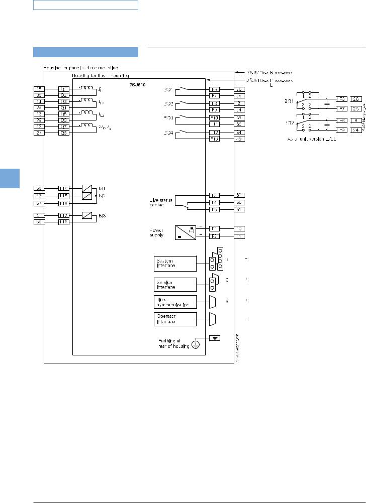
Connection diagram
5
Fig. 5/94
7SJ610 connection diagram
*) For pinout of communication ports see part 17 of this catalog.
For the allocation of the terminals of the panel surface-mounting version refer to the manual (http://www.siprotec.com).
5/102 |
Siemens SIP · 2008 |
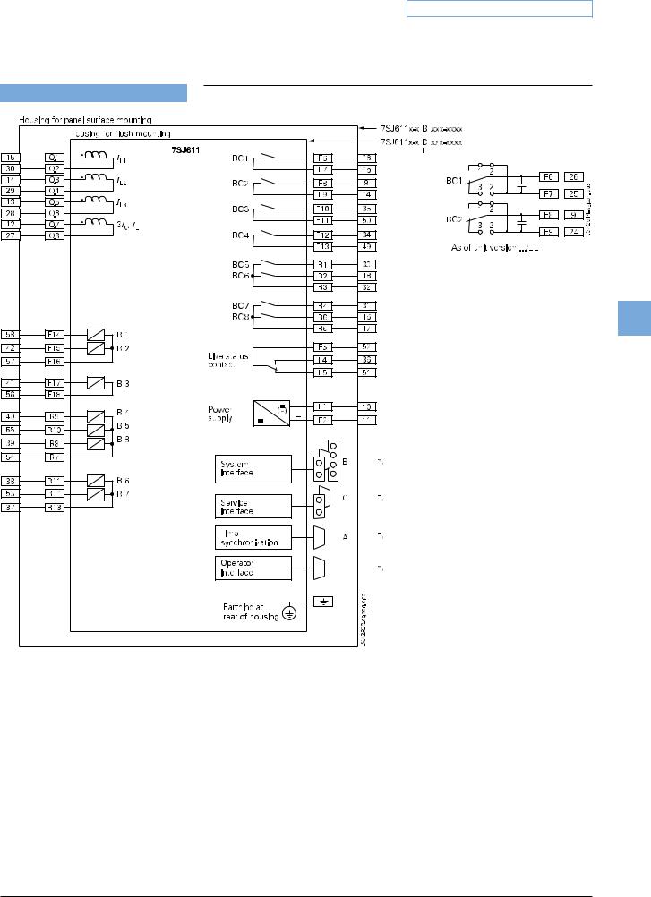
5 Overcurrent Protection / 7SJ61
Connection diagram
5
Fig. 5/95
7SJ611 connection diagram
*) For pinout of communication ports see part 17 of this catalog.
For the allocation of the terminals of the panel surface-mounting version refer to the manual (http://www.siprotec.com).
Siemens SIP · 2008 |
5/103 |

5 Overcurrent Protection / 7SJ61
Connection diagram
5
Fig. 5/96
7SJ612 connection diagram
*) For pinout of communication ports see part 17 of this catalog.
For the allocation of the terminals of the panel surface-mounting version refer to the manual (http://www.siprotec.com).
5/104 |
Siemens SIP · 2008 |
5 Overcurrent Protection / 7SJ61
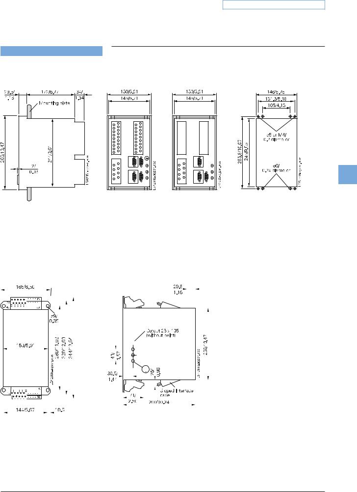
Dimension drawings in mm / inch
Dimension drawings for SIPROTEC 4 1/3 x 19" housing (7XP20)
5
|
|
|
|
|
|
|
|
|
|
|
Side view |
Rear view |
|
|
Rear view |
Panel cutout |
|||||||||||||||||||||||||||||||||||||||||||||||||||
|
|
|
|
|
|
|
|
|
|
|
|
|
|
|
|
|
|
|
|
|
|
|
|
|
|
|
|
|
|
|
|
|
|
|
7SA610, 7SD61, 7SJ64 |
|
|
7SJ61, 7SJ62, 7UT612, |
|
||||||||||||||||||||||||||||
Fig. 17/24 |
|
|
|
|
|
|
|
|
|
|
|
|
|
|
|
|
|
|
|
|
|
7UM611 |
|
||||||||||||||||||||||||||||||||||||||||||||
|
|
|
|
|
|
|
|
|
|
|
|
|
|
|
|
|
|
|
|
|
|
|
|
|
|
|
|
|
|
|
|
|
|||||||||||||||||||||||||||||||||||
Housing for panel flush mounting/ |
|
|
|
|
|
|
|
|
|
|
|
|
|
|
|
|
|
|
|
|
|
|
|
|
|
|
|
|
|
|
|
|
|
||||||||||||||||||||||||||||||||||
cubicle mounting (1/3 x 19") |
|
|
|
|
|
|
|
|
|
|
|
|
|
|
|
|
|
|
|
|
|
|
|
|
|
|
|
|
|
|
|
|
|
||||||||||||||||||||||||||||||||||
|
|
|
|
|
|
|
|
|
|
|
|
|
|
|
|
|
|
|
|
|
|
|
|
|
|
|
|
|
|
|
|
|
|
|
|
|
|
|
|
|
|
|
|
|
|
|
|
|
|
|
|
|
|
|
|
|
|
|
|
|
|
|
|
|
|
|
|
|
|
|
|
|
|
|
|
|
|
|
|
|
|
|
|
|
|
|
|
|
|
|
|
|
|
|
|
|
|
|
|
|
|
|
|
|
|
|
|
|
|
|
|
|
|
|
|
|
|
|
|
|
|
|
|
|
|
|
|
|
|
|
|
|
|
|
|
|
|
|
|
|
|
|
|
|
|
|
|
|
|
|
|
|
|
|
|
|
|
|
|
|
|
|
|
|
|
|
|
|
|
|
|
|
|
|
|
|
|
|
|
|
|
|
|
|
|
|
|
|
|
|
|
|
|
|
|
|
|
|
|
|
|
|
|
|
|
|
|
|
|
|
|
|
|
|
|
|
|
|
|
|
|
|
|
|
|
|
|
|
|
|
|
|
|
|
|
|
|
|
|
|
|
|
|
|
|
|
|
|
|
|
|
|
|
|
|
|
|
|
|
|
|
|
|
|
|
|
|
|
|
|
|
|
|
|
|
|
|
|
|
|
|
|
|
|
|
|
|
|
|
|
|
|
|
|
|
|
|
|
|
|
|
|
|
|
|
|
|
|
|
|
|
|
|
|
|
|
|
|
|
|
|
|
|
|
|
|
|
|
|
|
|
|
|
|
|
|
|
|
|
|
|
|
|
|
|
|
|
|
|
|
|
|
|
|
|
|
|
|
|
|
|
|
|
|
|
|
|
|
|
|
|
|
|
|
|
|
|
|
|
|
|
|
|
|
|
|
|
|
|
|
|
|
|
|
|
|
|
|
|
|
|
|
|
|
|
|
|
|
|
|
|
|
|
|
|
|
|
|
|
|
|
|
|
|
|
|
|
|
|
|
|
|
|
|
|
|
|
|
|
|
|
|
|
|
|
|
|
|
|
|
|
|
|
|
|
|
|
|
|
|
|
|
|
|
|
|
|
|
|
|
|
|
|
|
|
|
|
|
|
|
|
|
|
|
|
|
|
|
|
|
|
|
|
|
|
|
|
|
|
|
|
|
|
|
|
|
|
|
|
|
|
|
|
|
|
|
|
|
|
|
|
|
|
|
|
|
|
|
|
|
|
|
|
|
|
|
|
|
|
|
|
|
|
|
|
|
|
|
|
|
|
|
|
|
|
|
|
|
|
|
|
|
|
|
|
|
|
|
|
|
|
|
|
|
|
|
|
|
|
|
|
|
|
|
|
|
|
|
|
|
|
|
|
|
|
|
|
|
|
|
|
|
|
|
|
|
|
|
|
|
|
|
|
|
|
|
|
|
|
|
|
|
|
|
|
|
|
|
|
|
|
|
|
|
|
|
|
|
|
|
|
|
|
|
|
|
|
|
|
|
|
|
|
|
|
|
|
|
|
|
|
|
|
|
|
|
|
|
|
|
|
|
|
|
|
|
|
|
|
|
|
|
|
|
|
|
|
|
|
|
|
|
|
|
|
|
|
|
|
|
|
|
|
|
|
|
|
|
|
|
|
|
|
|
|
|
|
|
|
|
|
|
|
|
|
|
|
|
|
|
|
|
|
|
|
|
|
|
|
|
|
|
|
|
|
|
|
|
|
|
|
|
|
|
|
|
|
|
|
|
|
|
|
|
|
|
|
|
|
|
|
|
|
|
|
|
|
|
|
|
|
|
|
|
|
|
|
|
|
|
|
|
|
|
|
|
|
|
|
|
|
|
|
|
|
|
|
|
|
|
|
|
|
|
|
|
|
|
|
|
|
|
|
|
|
|
|
|
|
|
|
|
|
|
|
|
|
|
|
|
|
|
|
|
|
|
|
|
|
|
|
|
|
|
|
|
|
|
|
|
|
|
|
|
|
|
|
|
|
|
|
|
|
|
|
|
|
|
|
|
|
|
|
|
|
|
|
|
|
|
|
|
|
|
|
|
|
|
|
|
|
|
|
|
|
|
|
|
|
|
|
|
|
|
|
|
|
|
|
|
|
|
|
|
|
|
|
|
|
|
|
|
|
|
|
|
|
|
|
|
|
|
|
|
|
|
|
|
|
|
|
|
|
|
|
|
|
|
|
|
|
|
|
|
|
|
|
|
|
|
|
|
|
|
|
|
|
|
|
|
|
|
|
|
|
|
|
|
|
|
|
|
|
|
|
|
|
|
|
|
|
|
|
|
|
|
|
|
|
|
|
|
|
|
|
|
|
|
|
|
|
|
|
|
|
|
|
|
|
|
|
|
|
|
|
|
|
|
|
|
|
|
|
|
|
|
|
|
|
|
|
|
|
|
|
|
|
|
|
|
|
|
|
|
|
|
|
|
|
|
|
|
|
|
|
|
|
|
|
|
|
|
|
|
|
|
|
|
|
|
|
|
|
|
|
|
|
|
|
|
|
|
|
|
|
|
|
|
|
|
|
|
|
|
|
|
|
|
|
|
|
|
|
|
|
|
|
|
|
|
|
|
|
|
|
|
|
|
|
|
|
|
|
|
|
|
|
|
|
|
|
|
|
|
|
Front view |
Side view |
Fig. 17/25
1/3 x 19” surface-mounting housing, terminals at top and bottom
Siemens SIP · 2008 |
5/105 |