

Connecting the Arduino to Your TV Set • 131
resistor values—75Ω, 470Ω, and 1kΩ, in our case. If you set both input signals to 0V, the output voltage will be 0V, too. That’s how we can create the SYNC signal.
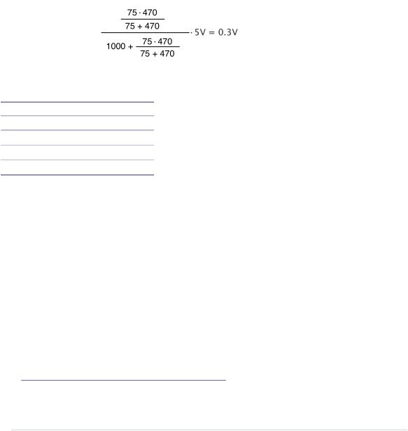
Calculating the output voltage for the remaining three combinations of input values isn’t rocket science, but the theory and formulas of voltage division are beyond the scope of this book. Just to give you a feeling, the following figure shows how to calculate the output voltage when you set D7 to 0V and D9 to 5V.
The following table shows the corresponding output voltages for all possible combinations of pin values.
Pin D7 |
Pin D9 |
Output Voltage |
Color |
0V |
0V |
0.0V |
SYNC |
0V |
5V |
0.3V |
Black |
5V |
0V |
0.65V |
Gray |
5V |
5V |
0.95V |
White |
Now you should see why we’ve used a 470Ω and a 1kΩ resistor. The value 1000 is roughly 470 times 2, so the resistor values follow the rules of a binary-weighted DAC. Also, these two resistors (combined with the TV set’s 75Ω resistor) produce the output voltages we need. Note that the output voltages don’t exactly match the specification, but in practice the small differences are negligible.
Connecting the Arduino to Your TV Set
Even with a digital-to-analog converter in place, we still have a problem: the Arduino doesn’t have an RCA jack—that is, you cannot plug an RCA cable into an Arduino. We could attach an RCA jack to a breadboard and connect it to the Arduino, but there’s an easier solution. We’ll modify an RCA cable and connect it directly to the Arduino.
First, you have to cut off one of the cable’s connectors using a wire cutter. (See Learning How to Use a Wire Cutter, on page 243, to learn more about wire cutters.) Then remove about three centimeters of the cable’s outer insulation.
report erratum • discuss
Chapter 8. Generating Video Signals with an Arduino • 132
Be careful, because the insulation isn’t very thick. Use the wire cutter to cut it slightly and then remove it by pushing it slowly toward the cable’s end. The cable should look like the following image.
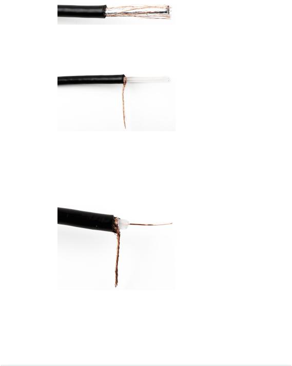
As you can see, there’s a mesh of wires below the outer insulation. Bring back the mesh into wire shape by rubbing it between your thumb and forefinger, so you can solder it to a solid-core wire later. The result should look like the following image.
The cable usually also contains an inner insulation made of plastic. Use the wire cutter again to remove the inner insulation. In my experience, it’s best to put the insulation between the wire cutter’s blades and then turn the cable slowly and carefully, increasing the pressure while turning the cable. Be very careful that you don’t accidentally cut the signal wire! After you’ve cut through the whole insulation, you can easily remove it. You should now see the cable’s signal wire, and your cable should look like the following image.
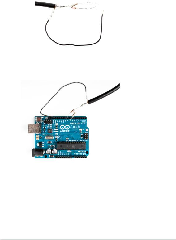
Finally, we have to connect the two resistors to the RCA cable’s signal wire, and it’s not sufficient to simply knot them together. You have to solder them. While you’re at it, connect the RCA cable’s ground wire to a piece of solid-core wire, so you can easily attach it to the Arduino. The following image shows what it should look like.
report erratum • discuss
Using the TVout Library • 133
That’s it! You’ve turned an RCA cable into a binary-weighted DAC that you can can connect to your Arduino to generate your own video signal. Plug the 470Ω resistor into port D7, the 1kΩ resistor into D9, and the ground wire into one of the Arduino’s GND ports. You can see the final circuit in the following image.
Using the TVout Library
Okay, the hardware’s done, but how do we bring it to life? We could try to write our own library to emit video signals, but I have to admit that I didn’t tell you the whole truth. To generate a clean and stable video signal, you not only have to output different voltages, but you also have to make sure that you emit your signals according to a very accurate schedule. The timing has to be so accurate that you have to implement it in assembly language!
report erratum • discuss
Chapter 8. Generating Video Signals with an Arduino • 134
Don’t worry! Of course there’s a library for that. The TVout library3 not only generates crystal-clear video signals, but also comes with a lot of utility functions for drawing geometric shapes. On top of that, it supports different fonts in several sizes.
Note that the TVout library doesn’t support every Arduino board. For example, it won’t work on the Arduino Leonardo or the Arduino Due. Check the TVout’s website for a list of compatible hardware.
Download TVout,4 unzip it, and copy the contents of the zip archive to the libraries folder of the Arduino IDE. Then restart your IDE.
The library comes with a few examples. The most important ones are DemoNTSC and DemoPAL. In principle, it’s only one example that demonstrates all of the library’s features, but it comes in two flavors: NTSC and PAL. This is necessary because there are different standards for analog TV. NTSC and PAL are two very popular ones. They don’t differ much, and modern TV sets are usually capable of working with both. Still, your TV set might be pickier about its input. If you’re living in the United States, you’ll probably need the NTSC demo; in Europe, PAL is the way to go.
Compile and upload the sketch to your Arduino; then connect the Arduino to your TV set’s composite input using the RCA cable. You should see an impressive demo showing TVout’s capabilities. At the end it even shows the inevitable rotating 3D cube.
The library’s standard example shows nearly all of
TVout’s functions in action, so it’s a good idea to have
a look at the code. Still, the best way to learn how to use the library is to write your own code. In the next section, you’ll create a graphical thermometer that displays the current temperature on your TV screen.
Building a TV Thermometer
To build our TV thermometer, we’ll use the TMP36 sensor again, so we’ll combine the circuit we created in Increasing Precision Using a Temperature Sensor, on page 86, with the circuit we created for generating the video signal. You can see the result in Figure 24, Circuit of the TV thermometer, on page 135.
3.https://code.google.com/p/arduino-tvout/
4.https://arduino-tvout.googlecode.com/files/TVoutBeta1.zip
report erratum • discuss
Building a TV Thermometer • 135
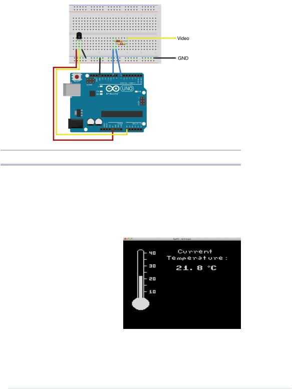
Figure 24—Circuit of the TV thermometer
Don’t get confused by what the circuit for the video signal looks like in the circuit diagram. That’s how you would build the circuit on a breadboard. Of course, you can still connect the modified RCA cable directly to the Arduino. Then connect the circuit for the TMP36 sensor.
Before we dive into the project’s code, have a look at what we’re trying to build.
On the left side of the screen, you see a graphical representation of a typical thermometer. It has a scale ranging from 5.5 to 40 degrees Celsius. The thermometer isn’t a static image. The bar in the middle will grow or shrink depending on the current temperature.
On the right side of the screen, we display the current temperature as text. All in all, we have to output some
text, and we have to draw some graphics. It’s a perfect opportunity to meet TVout’s most important functions, so let’s see how it works.
report erratum • discuss

Chapter 8. Generating Video Signals with an Arduino • 136
Video/TvThermometer/TvThermometer.ino
#include <TVout.h> #include <fontALL.h> #include "thermometer.h"
const float SUPPLY_VOLTAGE = 5.0; const float MIN_TEMP = 5.5; const float MAX_TEMP = 40.0;
const unsigned int SCREEN_WIDTH = 120; const unsigned int SCREEN_HEIGHT = 96; const unsigned int TEMP_SENSOR_PIN = A0; const unsigned int SCALE_X_MIN = 8; const unsigned int SCALE_Y_MIN = 6; const unsigned int SCALE_Y_MAX = 75; const unsigned int SCALE_WIDTH = 3;
const unsigned int SCALE_HEIGHT = SCALE_Y_MAX - SCALE_Y_MIN;
float current_temperature = 0.0;
unsigned long last_measurement = millis(); TVout TV;
At the beginning of our program, we include a few header files. TVout.h declares TVout’s main class and all of its methods. fontALL.h contains the definition of all fonts that TVout offers. If you don’t want to output any text, you don’t have to include it. The thermometer.h file makes the graphical representation of our thermometer available to our program. I’ll explain its content later.
After we’ve included all necessary header files, we define a few constants and variables:
•SUPPLY_VOLTAGE defines the Arduino’s supply voltage, and TEMP_SENSOR_PIN contains the number of the pin to which you’ve connected the TMP36 sensor.
•MIN_TEMP and MAX_TEMP define the minimum and maximum temperatures (in degrees Celsius) that the TV thermometer can display.
•SCREEN_WIDTH and SCREEN_HEIGHT define the screen’s width and height. Note that the Arduino isn’t capable of displaying really big screen resolutions. A width of 120 to 132 pixels and a height of 96 pixels is a reasonable compromise.
•SCALE_X_MIN defines the minimum X position of the thermometer’s scale.
SCALE_Y_MIN and SCALE_Y_MAX define the minimum and maximum Y positions of the thermometer’s scale. We’ll need these constants to draw a rectangle representing the current temperature later.
report erratum • discuss

Building a TV Thermometer • 137
•SCALE_WIDTH and SCALE_HEIGHT define the width and height of the thermometer’s scale.
•The variable current_temperature holds the last temperature we measured. last_measurement contains the time stamp in milliseconds when we last measured the current temperature. We need this because we don’t want to measure the temperature permanently, but only every few seconds.
•TV is an instance of the TVout class, and we’ll use it for accessing the TV screen using the Arduino.
Next we define the setup function:
Video/TvThermometer/TvThermometer.ino void setup() {
TV.begin(PAL, SCREEN_WIDTH, SCREEN_HEIGHT); TV.bitmap(0, 1, thermometer); TV.select_font(font4x6);
TV.set_cursor(20, 4); TV.print("40"); TV.set_cursor(20, 24); TV.print("30"); TV.set_cursor(20, 44); TV.print("20"); TV.set_cursor(20, 64); TV.print("10");
}
We call the begin method of the TV object. We set the analog TV standard to PAL, and we set the screen’s width and height. If your TV set prefers NTSC, you have to replace the first argument with NTSC. After that, we invoke the bitmap method to draw the thermometer image to the screen. Its X position is 0, and its Y position is 1.
The thermometer’s image doesn’t contain numbers next to its scale, so we add the numbers in our program. Therefore, we have to select the font we’re going to use by using the select_font method. TVout’s font capabilities are quite impressive. It comes with three fixed-width fonts (4x6, 6x8, and 8x8 pixels) that are sufficient for most purposes. It also supports variable-width fonts, and it even allows you to define your own. Here we use a font that’s 4 pixels wide and 6 pixels high. The set_cursor method moves the cursor to a certain screen position, and print prints text to the current cursor position.
The loop function implements the rest of our thermometer’s business logic.
report erratum • discuss

Chapter 8. Generating Video Signals with an Arduino • 138
Video/TvThermometer/TvThermometer.ino
Line 1 void loop() {
-unsigned long current_millis = millis();
-if (abs(current_millis - last_measurement) >= 1000) {
-current_temperature = get_temperature(); 5 last_measurement = current_millis;
-int y_pos = mapfloat(
-current_temperature, MIN_TEMP, MAX_TEMP, SCALE_Y_MAX, SCALE_Y_MIN);
-TV.draw_rect(
-SCALE_X_MIN, SCALE_Y_MIN, SCALE_WIDTH, SCALE_HEIGHT, BLACK, BLACK);
10 TV.draw_rect(
-SCALE_X_MIN, y_pos, SCALE_WIDTH, SCALE_Y_MAX - y_pos, WHITE, WHITE);
-TV.select_font(font6x8);
-TV.set_cursor(53, 1);
-TV.print("Current");
15 TV.set_cursor(40, 11);
-TV.print("Temperature:");
-TV.select_font(font8x8);
-TV.set_cursor(50, 25);
-TV.print(current_temperature, 1); 20 TV.print(" C");
-TV.draw_circle(88, 27, 1, WHITE);
-}
-}
-
25 const float mapfloat(
-float x, float in_min, float in_max, float out_min, float out_max)
-{
-return (x - in_min) * (out_max - out_min) / (in_max - in_min) + out_min;
-}
30
-const float get_temperature() {
-const int sensor_voltage = analogRead(TEMP_SENSOR_PIN);
-const float voltage = sensor_voltage * SUPPLY_VOLTAGE / 1024;
-return (voltage * 1000 - 500) / 10;
35 }
We make sure that we measure the current temperature only once per second. Whenever we determine the current temperature, we calculate the new upper Y position of the thermometer’s scale in line 6. The map_float function maps the current temperature to a value on our thermometer’s scale.
Then we use the draw_rect method (which draws a rectangle on the screen) twice. The first call erases the thermometer’s scale completely. This is necessary because the temperature can rise or fall. We could clear and redraw the whole screen every time, but that would be overkill. The second call draws a white rectangle on our scale that represents the current temperature.
report erratum • discuss