


CHAPTER 8
Generating Video Signals with an Arduino
So far we’ve used several different technologies to communicate with the outside world. We’ve used LEDs to represent our binary die’s results, for example, and we’ve used the serial port to send more elaborate messages. We’ve also turned data received on the serial port into shiny applications running in our browser.
For many projects this way of displaying information is sufficient, but in some cases you want a real display. You could use an LCD display, for example, and you’ll find multicolor TFT touch displays you can attach to the Arduino, too. Another option is surprisingly cheap: you can connect the Arduino to your TV set and display information right on the screen.
In this chapter, not only will you learn how analog TV works in principle, you’ll also learn how to generate a stable monochrome video signal using your Arduino. At the end of the chapter, you’ll have a graphical thermometer that will run on the TV set in your living room.
report erratum • discuss
Chapter 8. Generating Video Signals with an Arduino • 128
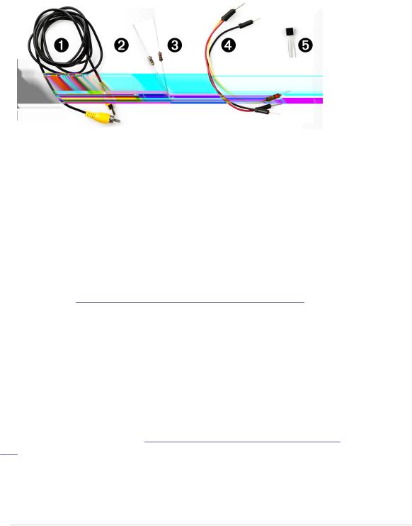
What You Need
1.An RCA cable
2.A 470Ω resistor
3.A 1kΩ resistor
4.Some wires
5.A TMP36 temperature sensor from Analog Devices
6.An Arduino board, such as the Uno, Duemilanove, or Diecimila
7.A USB cable to connect the Arduino to your computer
How Analog Video Works
Before you create your own video signals, it helps to understand how analog TV systems work in general. If you’re impatient, you can skip the theory and jump straight to Connecting the Arduino to Your TV Set, on page 131.
First of all, you should note that analog video is completely different from digital video in most regards. In this chapter, we’ll only talk about analog video signals that you can feed to your TV set’s composite input.
You might remember the good old days when TV sets were huge, heavy boxes with ridiculously tiny screens. These boxes had to be so big because they contained a small electron cannon that produced images by firing electrons to the screen. The cannon drew an image line by line—that is, it started at the top-left corner of the screen and drew the first line of the image. At the end of the line, it moved back to the left side and drew the second line. This technique is called raster scan. Figure 23, How raster scan works, on page 129 shows how it worked.
After the last line was drawn, the electron beam moved back to the top and drew the next image. Depending on the TV standard, this process happened
report erratum • discuss

How Analog Video Works • 129
Figure 23—How raster scan works
(Image created by Ian Harvey)
50 to 60 times per second, and it was fast enough to create the illusion of motion. (Actually, most TV sets needed two passes to draw a single image using a mechanism called interlacing, but for our purposes that’s irrelevant.)
Moving the electron beam across the screen isn’t sufficient. You have to somehow encode the information you’d like to draw. Therefore, you have to change the electron beam’s intensity while it traverses the screen. Due to a chemical reaction, the TV screen will glow in different colors when the electron cannon hits it with different intensities. For a monochrome signal, you need to generate the voltages explained in the following table.
Voltage: 0.0V 0.3V 0.6V 1.0V
Color: SYNC Black Gray White
A voltage of 0V represents the SYNC signal. It tells the TV set that a new line of the image begins. All the other voltages represent different colors. To draw a white dot, you have to set the voltage to 1V.
All we have to do is create a couple of different voltage levels. That doesn’t sound too difficult, but unfortunately, the Arduino has only analog input pins. It cannot emit analog output signals. At least not directly, but in the next section you’ll learn how to do it.
report erratum • discuss
Chapter 8. Generating Video Signals with an Arduino • 130
Building a Digital-to-Analog Converter (DAC)
The Arduino doesn’t natively support analog output signals, so we need to find a way around this limitation. The solution is a digital-to-analog converter (DAC).1 As the name suggests, such a circuit turns a digital input into an analog output. You can find DACs in a lot of consumer devices—for example, in your MP3 player. It turns your digitally encoded music into an analog sound wave.
One of the most important characteristics of a DAC is its resolution. In our case we need to generate four different voltage levels to create a video signal. To encode four voltage levels, we need two bits—that is, our DAC has a 2-bit resolution. The following table shows how we could map the four binary input values to their voltage levels.
Binary input: |
00 |
01 |
10 |
11 |
Output voltage: 0.0V 0.3V 0.6V 1.0V
We can use two of the Arduino’s digital pins to control the DAC’s input value, but we still have to find a way to generate different voltages depending on the pins’ values.
There are several ways to achieve this, but one of the easiest is by using a binary-weighted DAC. It has the following characteristics:
•You need a resistor for every input bit.
•All resistors have to be in parallel.
•Resistor value for bit #0 is R. For bit #1 it’s 2R, for bit #3 it’s 4R, and so on.
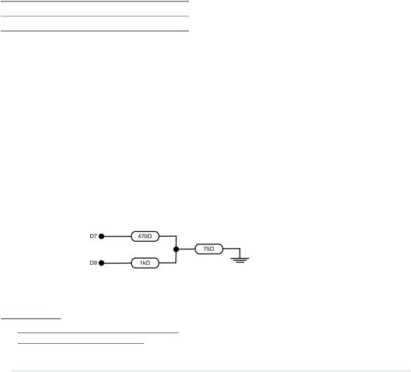
Let’s say we use the Arduino’s digital pins D7 and D9 to control the DAC’s input value. In the following figure, you can see our DAC’s circuit. You have to add the 470Ω and 1kΩ resistors yourself, but you get the 75Ω resistor for free, because it’s part of your TV set’s input connector.
In principle, the binary-weighted DAC is a voltage divider2—that is, it turns an input voltage into a smaller voltage. The output voltage depends on the
1.http://en.wikipedia.org/wiki/Digital-to-analog_converter
2.http://en.wikipedia.org/wiki/Voltage_divider
report erratum • discuss