


CHAPTER 3
Building Binary Dice
Things will really start to get interesting now that you’ve learned the basics of Arduino development. You now have the skills to create your first complex, stand-alone projects. After you’ve worked through this chapter, you’ll know how to work with LEDs, buttons, breadboards, and resistors. Combining these parts with an Arduino gives you nearly endless opportunities for new and cool projects.
Our first project will be creating an electronic die. While regular dice display their results using one to six dots, ours will use LEDs instead. For our first experiments, a single LED was sufficient, but for the dice we need more than one. You need to connect several external LEDs to the Arduino. Because you cannot attach them all directly to the Arduino, you’ll learn how to work with breadboards. Also, you need a button that rolls the dice, so you’ll learn how to work with pushbuttons, too. To connect pushbuttons and LEDs to the Arduino, you need another important electronic part: the resistor. At the end of the chapter, you’ll have many new tools in your toolbox.
What You Need
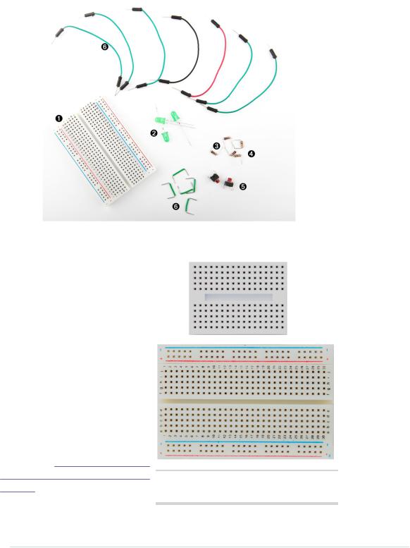
1.A half-size breadboard
2.Three LEDs (for the exercises you’ll need additional LEDs)
3.Two 10kΩ resistors (see Current, Voltage, and Resistance, on page 239, to learn more about resistors)
4.Three 1kΩ resistors
5.Two pushbuttons
6.Some wires of different lengths
7.An Arduino board, such as the Uno, Duemilanove, or Diecimila
8.A USB cable to connect the Arduino to your computer
report erratum • discuss
Chapter 3. Building Binary Dice • 40
Working with Breadboards
Connecting parts directly to the Arduino is an option only in the simplest cases. Usually, you’ll prototype your projects on a breadboard that you connect to the Arduino. A breadboard is like a circuit board, but you don’t have to solder parts to it; instead, you simply plug them in.
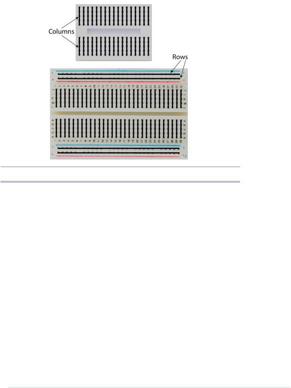
All breadboards work the same way. They have a lot of sockets you can use for plugging in through-hole parts or wires. That alone wouldn’t be a big deal, but the sockets are connected in a special way. Figure 9, How sockets
on a breadboard are connected, on Figure 8— Breadboards come in various types page 41 shows how.
and sizes—the picture shows two.
report erratum • discuss
Using an LED on a Breadboard • 41
Figure 9—How sockets on a breadboard are connected
As you can see, most sockets are connected in columns. If one socket of a column is connected to a power supply, then automatically all the other sockets in this column are powered, too. On the bigger board in the photo, you can also see four rows of connected sockets. This is convenient for bigger circuits. Usually, you connect one row to your power supply and one to the ground. This way, you can distribute power and ground to any point on the board. Note that on some breadboards there are gaps between the sockets on a single row. On such breadboards you have to bridge the gaps using a wire if needed.
Now let’s see how to put parts on a breadboard.
Using an LED on a Breadboard
Up to now, we used the status LED that is installed on the Arduino board. This LED is nice for testing purposes, but it’s only sufficient for trivial electronics projects. Also, it’s very small and not very bright, so it’s a good idea to get some additional LEDs and learn how to connect them to the Arduino. It’s really easy.
report erratum • discuss
Chapter 3. Building Binary Dice • 42
We won’t use the same type of LEDs that are mounted on the Arduino board. They are surface-mounted devices (SMD) that are difficult to handle. At the beginning of your electronics career, you will rarely work with SMD parts, because for most of them you need special equipment and a lot of experience. They save costs as soon as you start mass production of an electronic device, but pure hobbyists won’t need them often.
The LEDs we need are through-hole parts. They are named through-hole parts because they are mounted to a circuit board through holes. That’s why they usually have one or more long wires. First you put the wires through holes in a printed circuit
board. Then you usually bend, solder, and cut them to attach the part to the board. Where available, you can also plug them into sockets as you have them on the Arduino or on breadboards.
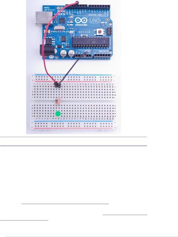
In this section you’ll learn how to work with LEDs on a breadboard. Figure 10, Connecting an LED on a breadboard to the Arduino, on page 43 shows our circuit. It consists of an Arduino, a breadboard, an LED, three wires, and a 1kΩ resistor. (More on that part in a few minutes.) Connect the Arduino to the breadboard using two wires. Connect pin 12 with the ninth column of the breadboard, and connect the ground pin with the tenth column. This automatically connects all sockets in column 9 to pin 12 and all sockets in column 10 to the ground. This choice of columns was arbitrary; you could’ve used other columns instead.
Plug the LED’s negative connector (the shorter one) into column 10 and its positive connector into column 9. When assembling an electronics project, parts fall into two categories: those you can mount any way you like and those that need a special direction. An LED has two connectors: an anode (positive) and a cathode (negative). It’s easy to mix them up, and my science teacher taught me the following mnemonic: the cathode is necative. It’s also easy to remember what the negative connector of an LED is: it is shorter, minus, less than. If you are a more positive person, then think of the anode as being bigger, plus, more. You can alternatively identify an LED’s connectors using its case. On the negative side the case is flat, while it’s round on the positive side.
When you plug parts or wires into a breadboard, you have to press them firmly until they slip in. You might need more than one try, especially on new boards, and it’s often useful to shorten the connectors with a wire cutter before plugging them into the breadboard. Make sure you can still identify the negative and positive connectors after you’ve shortened them. Shorten
report erratum • discuss
Using an LED on a Breadboard • 43
Figure 10—Connecting an LED on a breadboard to the Arduino
the negative one a bit more. Also wear safety glasses to protect your eyes when you’re cutting the connectors!
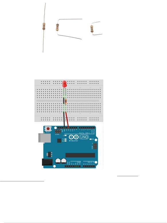
The things we’ve done up until now have been straightforward. That is, in principle we have only extended the Arduino’s ground pin and its IO pin number 12. Why do we have to add a resistor, and what is a resistor? A resistor limits the amount of current that flows through an electric connection. In our case, it protects the LED from consuming too much power, because this would destroy the LED. You always have to use a resistor when powering an LED! In Current, Voltage, and Resistance, on page 239, you can learn more about resistors and their color bands. The following image shows a resistor in various stages: unprocessed, bent, and cut. (See Learning How to Use a Wire Cutter, on page 243, to learn how to use a wire cutter.)
report erratum • discuss
Chapter 3. Building Binary Dice • 44
We don’t want to fiddle around too much with the connectors, so we build the circuit as shown in the following figure. That is, we use both sides of the breadboard by connecting them with a short wire. Note that the resistor bridges the sides, too.
To make the LED blink, we can use the same sketch we used in Meeting the Arduino IDE, on page 14. We only have to set LED_PIN to 12 instead of 13:
report erratum • discuss