

бакМИТ_КП2015 / Компоненты по вариантам / АЦП / MAX1177
.pdf16-Bit, 135ksps, Single-Supply ADC with 0 to 10V Input Range
Definitions
Integral Nonlinearity
Integral nonlinearity (INL) is the deviation of the values on an actual transfer function from a straight line. This straight line can be either a best-straight-line fit or a line drawn between the end points of the transfer function, once offset and gain errors have been nullified. The static linearity parameters for the MAX1177 are measured using the end-point method.
Differential Nonlinearity
Differential nonlinearity (DNL) is the difference between an actual step width and the ideal value of 1 LSB. A DNL error specification of 1 LSB guarantees no missing codes and a monotonic transfer function.
Signal-to-Noise Ratio
For a waveform perfectly reconstructed from digital samples, signal-to-noise ratio (SNR) is the ratio of the full-scale analog input (RMS value) to the RMS quantization error (residual error). The ideal, theoretical minimum analog-to-digital noise is caused by quantization noise error only and results directly from the ADC’s resolution (N bits):
SNR = (6.02 N + 1.76)dB
where N = 16 bits.
In reality, there are other noise sources besides quantization noise: thermal noise, reference noise, clock jitter, etc. The SNR is computed by taking the ratio of the RMS signal to the RMS noise, which includes all spectral components minus the fundamental, the first five harmonics, and the DC offset.
Signal-to-Noise Plus Distortion
Signal-to-noise plus distortion (SINAD) is the ratio of the fundamental input frequency’s RMS amplitude to the RMS equivalent of all the other ADC output signals:
|
SignalRMS |
|
|
SINAD(dB) = 20 log |
|
||
|
|||
|
(Noise + Distortion)RMS |
||
Effective Number of Bits
Effective number of bits (ENOB) indicates the global accuracy of an ADC at a specific input frequency and sampling rate. An ideal ADC error consists of quantization noise only. With an input range equal to the fullscale range of the ADC, calculate the ENOB as follows:
= SINAD −1.76
ENOB
6.02
Total Harmonic Distortion
Total harmonic distortion (THD) is the ratio of the RMS sum of the first five harmonics of the input signal to the fundamental itself. This is expressed as:
|
V 2 |
+ V |
2 + V |
2 + V 2 |
|
|
2 |
3 |
4 |
5 |
|
THD = 20 log |
|
|
|
|
|
|
|
V1 |
|
||
|
|
|
|
|
|
|
|
|
|
|
|
where V1 is the fundamental amplitude and V2 through V5 are the 2ndthrough 5th-order harmonics.
Spurious-Free Dynamic Range
Spurious-free dynamic range (SFDR) is the ratio of the RMS amplitude of the fundamental (maximum signal component) to the RMS value of the next-largest frequency component.
MAX1177
______________________________________________________________________________________ 11

MAX1177
16-Bit, 135ksps, Single-Supply ADC with to 10V Input Range
Functional Diagram
|
|
REFADJ |
HBEN |
AVDD |
AGND |
DVDD DGND |
|
|
5kΩ |
|
|
|
|
|
REFERENCE |
|
|
|
|
|
|
|
|
OUTPUT |
8 BITS |
8 BITS |
|
|
|
|
|
D0–D7 |
||
|
|
|
REGISTERS |
|
||
|
|
|
|
OR |
||
|
|
|
|
|
|
|
REF |
|
|
|
|
|
D8–D15 |
AIN |
INPUT |
CAPACITIVE |
|
|
|
|
SCALER |
DAC |
|
|
|
|
|
|
|
|
|
|
||
AGND |
|
|
|
|
MAX1177 |
|
|
CLOCK |
SUCCESSIVE- |
|
|
|
|
|
APPROXIMATION |
|
|
|
|
|
|
|
REGISTER AND |
|
|
|
EOC |
CS |
|
CONTROL LOGIC |
|
|
|
|
|
|
|
|
|
||
R/C |
|
|
|
|
|
|
|
|
|
|
|
|
Pin Configuration |
|
Chip Information |
||||||
|
|
|
|
|
|
|
|
|
|
|
|
|
|
TRANSISTOR COUNT: 15,383 |
TOP VIEW |
|
|
|
|
|
|
|
|
|
|
||||
|
|
|
|
|
|
|
|
|
|
|
PROCESS: BiCMOS |
|||
|
|
|
|
|
|
|
|
|
|
|
|
|
|
|
D4/D12 |
1 |
|
|
|
|
|
20 |
D3/D11 |
|
|
||||
|
|
|
|
|
|
|
|
|
|
|
|
|
|
|
D5/D13 |
2 |
|
|
|
|
|
19 |
D2/D10 |
|
|
||||
|
|
|
|
|
|
|
|
|
|
|
|
|
|
|
D6/D14 |
3 |
|
|
|
|
|
18 |
D1/D9 |
|
|
||||
|
|
|
|
|
|
|
|
|
|
|
|
|
|
|
D7/D15 |
4 |
|
|
|
|
|
17 |
D0/D8 |
|
|
||||
|
|
|
|
|
|
|
|
|
|
|
|
|
|
|
|
R/C |
5 |
MAX1177 |
16 |
DVDD |
|
|
|||||||
|
|
|
|
|
|
|
|
|
|
|||||
|
EOC |
|
6 |
|
|
|
|
|
15 |
DGND |
|
|
||
|
|
|
|
|
|
|
|
|
|
|
|
|
|
|
AVDD |
7 |
|
|
|
|
|
14 |
|
CS |
|
|
|
||
|
|
|
|
|
|
|
|
|
|
|
|
|
|
|
AGND |
8 |
|
|
|
|
|
13 |
HBEN |
|
|
||||
|
|
|
|
|
|
|
|
|
|
|
|
|
|
|
|
AIN |
9 |
|
|
|
|
|
12 |
REF |
|
|
|||
|
|
|
|
|
|
|
|
|
|
|
|
|
|
|
AGND |
10 |
|
|
|
|
|
11 |
REFADJ |
|
|
||||
|
|
|
|
|
|
|
|
|
|
|
|
|
|
|
TSSOP
12 ______________________________________________________________________________________
16-Bit, 135ksps, Single-Supply ADC with 0 to 10V Input Range
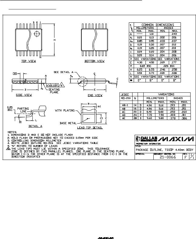
Package Information
(The package drawing(s) in this data sheet may not reflect the most current specifications. For the latest package outline information, go to www.maxim-ic.com/packages.)
TSSOP4.40mm.EPS |
MAX1177
Maxim cannot assume responsibility for use of any circuitry other than circuitry entirely embodied in a Maxim product. No circuit patent licenses are implied. Maxim reserves the right to change the circuitry and specifications without notice at any time.
Maxim Integrated Products, 120 San Gabriel Drive, Sunnyvale, CA 94086 408-737-7600 ____________________ 13
© 2003 Maxim Integrated Products |
Printed USA |
is a registered trademark of Maxim Integrated Products. |