

Bologna / 02_TCAD_laboratory_Sentaurus_TCAD_GBB_OLD
.pdfTechnology Computer Aided
Design (TCAD) Laboratory
Lecture 2, Overview of
Synopsys Sentaurus TCAD
[Source: Synopsys]
Giovanni Betti Beneventi
E-mail: gbbeneventi@arces.unibo.it ; giobettibeneventi@gmail.com
Office: Engineering faculty, ARCES lab. (Ex. 3.2 room), viale del Risorgimento 2, Bologna
Phone: +39-051-209-3773
Advanced Research Center on Electronic Systems (ARCES) University of Bologna, Italy
G. Betti Beneventi |
1 |

Outline
•Sentaurus Tools
•TCAD simulation flow
•Starting TCAD: Sentaurus Workbench
•Sentaurus Structure Editor
•Sentaurus Device
•Output examples
•Conclusion
G. Betti Beneventi |
2 |

Outline
Sentaurus Tools
•TCAD simulation flow
•Starting TCAD: Sentaurus Workbench
•Sentaurus Structure Editor
•Sentaurus Device
•Output examples
•Conclusion
G. Betti Beneventi |
3 |
Synopsys TCAD Sentaurus tools
•Synopsys TCAD Sentaurus is a software suite made by several tools (each one with its own programming language)
•The starting page of the Synopsys TCAD manual contains the link to the manual of each tool, and can be opened by typing
cd ~ ; source .ISErc ; man_sen &
G. Betti Beneventi |
4 |

Outline
• Sentaurus Tools
TCAD simulation flow
•Starting TCAD: Sentaurus Workbench
•Sentaurus Structure Editor
•Sentaurus Device
•Output examples
•Conclusion
G. Betti Beneventi |
5 |
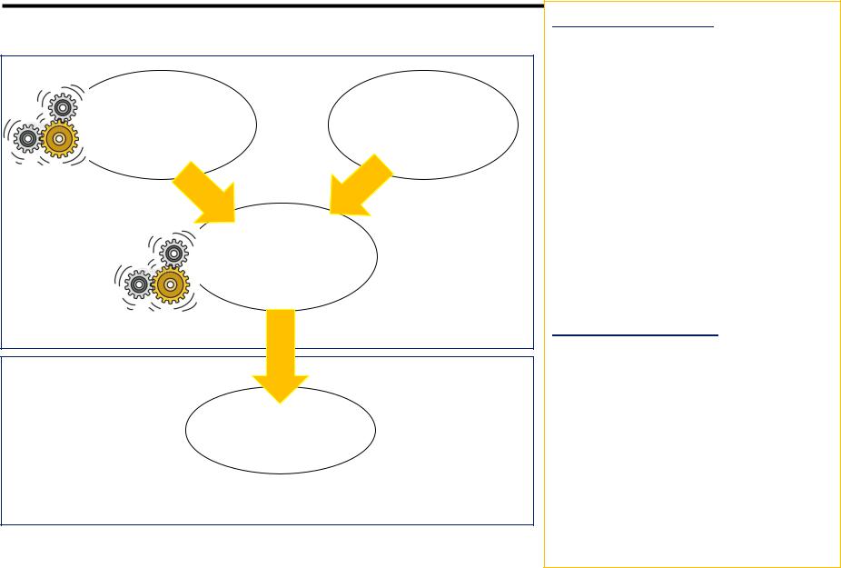
Modeling of semiconductor devices: typical flow
TCAD |
PROCESS |
|
PROCESS |
||
EMULATION |
||
SIMULATION |
||
|
TCAD
DEVICE
SIMULATION
TCAD DEVICE DESIGN
Spice-like
MODELING
COMPACT MODELING ENABLES CIRCUIT DESIGN
Process Emulation.
Process steps are not simulated but emulated, i.e. the device structure is realized through somewhat idealized procedures that mimic real process flow. Process emulation is used for first order device analysis (e.g. targeting a device for new specs., exploring new device concepts). Process simulations can be done once a new device architecture has been optimized by means of device simulation in order to (a) investigate process non-idealities, (b) target process specs.
Compact Modeling.
Compact modeling is a methodology strictly related to TCAD. Once the physics of the device has been verified by TCAD, the device electrical characteristics can be
“synthesized” by analytical functions that can be physically-based or simply behavioral. Compact modeling is needed to provide the
“device model cards” to the circuit
designers for circuit simulations. |
6 |
G. Betti Beneventi |
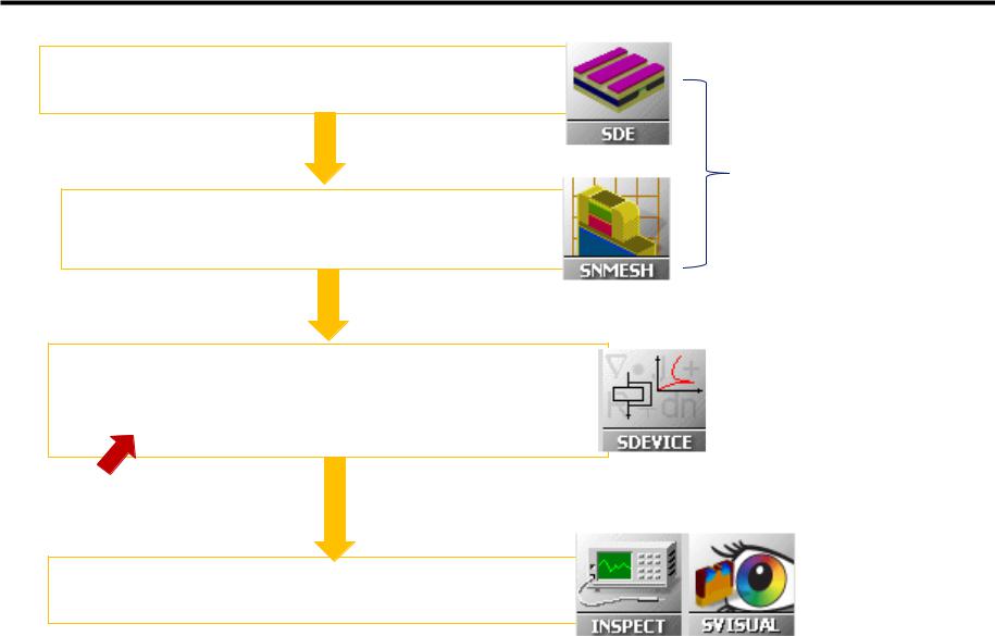
Going through the DEVICE SIMULATION steps
Getting the device geometry and doping concentrations (from process emulation)
Generating a grid (mesh) for numerical computation
Solve for Poisson equations and current continuity equations on the defined mesh
for some given boundary conditions
The description of physics goes there
Visualizing the results
(both electrical results than internal quantities)
PRE-
PROCESSING
PROCESSING
POST-
PROCESSING
G. Betti Beneventi |
7 |

Outline
•Sentaurus Tools
•TCAD simulation flow
Starting TCAD: Sentaurus Workbench
•Sentaurus Structure Editor
•Sentaurus Device
•Output examples
•Conclusion
G. Betti Beneventi |
8 |

Loading the TCAD environment under Linux
1. Loading the environment variables and aliases
cd ~
source .ISErc
.ISErc is a configuration file stored in the home directory which contains some useful commands and settings:
# environmental variables
setenv PATH "${PATH}:/sw/CAD/TCAD/I_2013.12/bin" setenv ISEROOT "/sw/CAD/TCAD/I_2013.12/bin" setenv LM_LICENSE_FILE 27000@taricone
setenv STDB "/grp-proj-ares/nano/gbbeneventi/TCAD" setenv OMP_NUM_THREADS 4
setenv NCPUS 4
tells OS where finding out TCAD software installation and executables
where user’s SWB projects reside
code parallelization
# .exe
alias swb "/sw/CAD/TCAD/I_2013.12/bin/swb"
# manuals
alias man_sen "acroread /sw/CAD/TCAD/I_2013.12/tcad/current/manuals/PDFManual/front.pdf"
alias to launch Sentaurus TCAD manual
2. Launch Sentaurus Workbench (without “killing” the terminal)
swb & |
alias to launch SWB |
|
G. Betti Beneventi |
9 |

Sentaurus Workbench: general information
•It is the main tool interface which can be Windows-like controlled
•From Sentaurus Workbench (SWB) all the simulation flow can be controlled
•Simulations trees with variation of parameters in a matrix organization can be created
•An instance in the SWB tool is called “Project”
•When a project is saved, a directory is created. ASCII files containing the details of the saved project are created in the directory (in particular the gtree.dat file contains the details of the simulation tree)
•Essential vocabulary to understand SWB operations:
–Scenario= to simplify the visualization, the whole simulation tree (the whole project) can be divided in more than one scenario (it means that one project can be divided in more trees)
–Tool= one of the Sentaurus TCAD tools (e.g. sde, sdevice, inspect, etc.).
–Parameter= a variable (it can be a dimension, a physical property, a logic flag..)
–Experiment= a row in the simulation matrix
–Node= a point of the simulation matrix. Each point of the matrix is a “node”.
•Real node: node that can be executed (one for each tool). They are colored according to the execution status of the corresponding simulation job
•Virtual node: node that cannot be executed
–Root= part of a row (i.e. of an experiment), from a given node to the left
–Leave= part of a row (i.e. of an experiment), from a given node to the right
G. Betti Beneventi 10