

Bologna / 03_TCAD_laboratory_Overview_of_Synopsys_Sentaurus_TCAD_GBB_20140402H1238
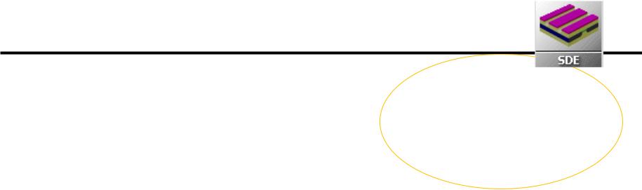
.pdfSentaurus Workbench: general information
•It is the main tool interface which can be Windows-like controlled
•From Sentaurus Workbench (SWB) all the simulation flow can be controlled
•Simulations trees with variation of parameters in a matrix organization can be created
•An instance in the SWB tool is called “Project”
•When a project is saved, a directory is created. ASCII files containing the details of the saved project are created in the directory (in particular the gtree.dat file contains the details of the simulation tree)
•Essential vocabulary to understand SWB operations:
–Scenario= to simplify the visualization, the whole simulation tree (the whole project) can be divided in more than one scenario (it means that one project can be divided in more trees)
–Tool= one of the Sentaurus TCAD tools (e.g. sde, sdevice, inspect, etc.).
–Parameter= a variable (it can be a dimension, a physical property, a logic flag..)
–Experiment= a row in the simulation matrix
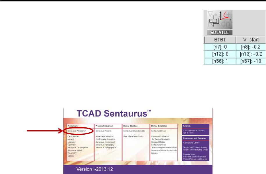
–Node= a point of the simulation matrix. Each point of the matrix is a “node”.
•Real node: node that can be executed (one for each tool). They are colored according to the execution status of the corresponding simulation job
•Virtual node: node that cannot be executed
–Root= part of a row (i.e. of an experiment), from a given node to the left
– Leave= part of a row (i.e. of an experiment), from a given node to the rightG. Betti Beneventi 11

Sentaurus Workbench: configuration and shortcuts
Project New Project Configuration Research
Research provides maximum flexibility, while Standard provides maximum level of consistency
Edit User Preferences Default View Options Show Pruned false
To prune a node means to cancel an experiment from the simulation tree
Scheduler Local jobs Maximum number of simultaneous jobs 10
The scheduler is the software tools which organizes the execution of the simulations
Scheduler Local jobs Default Nice Level 1
The lower the Default Nice Level (1 is the minimum value) the higher the priority by which the simulation is running by the operating systems
F5 refresh
CTRL-P node preprocessing ; CTRL-R: node running ; CTRL-T abort node execution
F6 edit parameter value in a node
F6 node explorer
F9 show/hide node number
G. Betti Beneventi 12

Sentaurus Workbench: useful commands
Project Operations Unlock
Unlock project blocking
Parameter Add
Add parameters
Experiments Create Default Experiments
To start a new trees: it creates the root experiment with default values parameters
Experiments Add New Experiment
To add a new experiment
[select a node] Nodes Extend Selection to Experiment Experiments
Add Values
To branch the trees by adding values to a selected experiment only
[select a node] Nodes Extend Selection to Leaves Nodes Prune
To cancel a branch in the experiment tree
G. Betti Beneventi 13
Sentaurus Workbench: use of @
To use parameters, those must be placed between a pair of @ in the tools command files (see later). Example: for the BTBT (Band-to-Band- Tunneling physical model) flag to be an Sdevice variable, in the Sdevice command file BTBT must be indicated as @BTBT@
The pre-processing steps basically writes how many files how many are the project’s experiments, in each of them substituting the @BTBT@ with the value of BTBT in the node corresponding to the given experiment.
Therefore, a pre-processing step is mandatory before an execution of a simulation
Although we have thoroughly review the most important feature, many other functionalities are available in SWB (to name a few: include Tcl code blocks, cut & paste scenario’s blocks, conformity checks): always refer to the user guide embedded in the manual front-page.
G. Betti Beneventi 14

Outline
•Sentaurus Tools
•TCAD simulation flow
•Starting TCAD: Sentaurus Workbench
Sentaurus Structure Editor
•Sentaurus Device
•Output examples
•Conclusion
G. Betti Beneventi 15
Sentaurus Structure Editor
•Tool that can be used for process emulation
•It allows defining
–device materials & geometry (1D,2D,3D) 
–doping
–contacts
N.B. 3D TCAD simulations are available in Sentaurus and much used especially by industry (need of precise results on particular application in which the device process/geometry is usually well known). On the other hand we will deal only with 2D simulations, for the sake of simplicity
•Within Sentaurus Structure Editor (SDE), the meshing operation must also be performed
•Better to use it in batch mode to increase program flexibility and power
•Input file where to write SDE command in text form must be named sde_dvs.cmd
•Once SDE is run, two files are produced:
nnodenumber_bnd.tdr for the visualization of the produced device geometry nnodenumber_msh.tdr to visualize the device geometry & the numerical mesh
•The difficult part about SDE is of course not programming in itself, but understanding and evaluating the simplification inherent to the idealized geometry drawings !
•Also the choice of the numerical mesh is sometimes not at all trivial (critical for the convergence of the numerical algorithm)
G. Betti Beneventi 16

Outline
•Sentaurus Tools
•TCAD simulation flow
•Starting TCAD: Sentaurus Workbench
•Sentaurus Structure Editor
Sentaurus Device
•Output examples
•Conclusion
G. Betti Beneventi 17
Sentaurus Device
•Tool that defines the partial differential equations to be solved, i.e. it defines the physical model (e.g. the drift-diffusion model, which consists in the Poisson equations and the current continuity equations)
•Boundary conditions (typically bias at the electrodes) must also be defined
•The material parameters of the physical model employed must be provided in a separate file
•It is possible to perform sweeps of the boundary conditions in order to get device electrical characteristics
•Also parameters for the numerical solvers implemented in the software must be defined
•Input files:
sdevice_des.cmd for physical models, boundary conditions and numerical parameters sdevice.par to enter the model material parameters
•Output files:
nnodenumber_des.tdr for the visualization of the simulated physical quantities on the domain nnodenumber.plt to visualize the device electrical characteristics
•The difficult part about Sdevice is not programming in itself but understands the simplification inherent to the chosen physical models !
•It is in general not trivial to understand which physical models must be included
•Also the choice of material parameters and of the numerical parameters can be challenging
G. Betti Beneventi 18
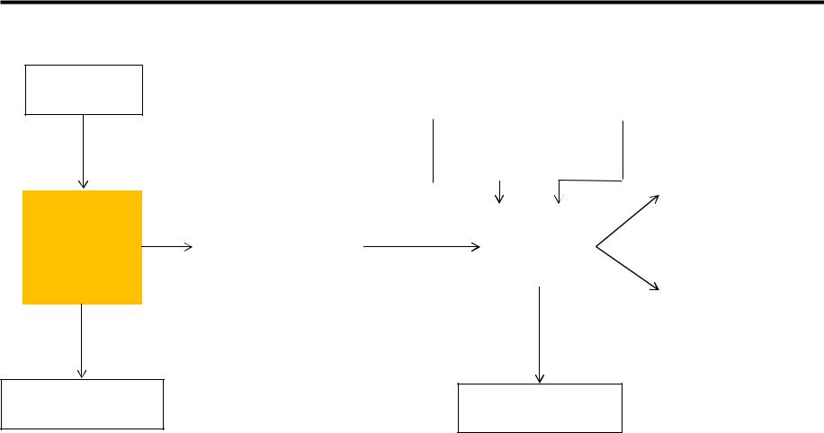
File naming conventions of SDE and Sdevice tools
command sde_dvs.cmd
Sentaurus Structure Editor (SDE)
output n@node@_dvs.out
command |
|
|
|
“parameter” file |
|
sdevice_des.cmd |
|
|
|
sdevice.par |
|
|
|
|
|
|
|
|
|
|
|
|
|
“plot” file |
|
|
|
|
|
|
|
(internal quantities) |
|
|
|
|
Sentaurus |
|
n@node@_des.tdr |
||
“grid” file |
|
|
|
|
|
||
|
|
|
Device |
|
|
|
|
n@node@_msh.tdr |
|
|
|
|
|
|
|
|
|
(Sdevice) |
|
|
|
||
|
|
|
|
“current” file |
|
||
|
|
|
|||||
|
|
|
|
|
|
|
|
|
|
|
|
|
|
(electrical |
|
|
|
|
|
|
|
characteristics) |
|
|
|
|
|
|
|
n@node@_des.plt |
|
|
|
|
|
|
|
|
|
output n@node@_des.out
G. Betti Beneventi 19

The manuals: where is the description of the device physics?
G. Betti Beneventi 20