

РЕГЛАМЕНТ англ
.pdf
|
71 |
© 2011 SAE International. All Rights Reserved |
2012 Formula SAE Rules |

|
APPENDIX AF - ALTERNATIVE FRAME RULES |
AF1 |
General Requirements |
|
These alternative structural requirements are intended to provide teams an alternative approach to the |
|
existing rules. The goal of these alternative rules is to provide a simpler alternative for monocoque |
|
designs and provide expanded design freedom for space frames and monocoques alike. The intent is |
|
not to alter allowable structures but to change the requirement process for showing compliance with |
|
the rules. |
|
Note: Generally SI units are used in these alternative frame rules with some dual references. |
AF1.1 |
Unless listed below under section AF7 “Non-Applicable Rules” all requirements of the rest of the |
|
rules apply in these alternative requirements. |
AF1.2 |
The AF Rules are considered a work in progress. As such, the Rules Committee and reviewers of the |
|
SRCF (below) may, at any time, amend and clarify these rules to maintain the spirit in which they |
|
were written and close any unintended loop holes. |
AF1.3 |
These rules are recommended for existing teams who have experience designing, constructing and |
|
competition with vehicles in the past. There is no experience requirement. |
AF1.4 |
Notice of Intent - Teams planning to build a vehicle to this alternative rule set for entry into a North |
|
American competition must notify the Rules Committee of their intent by November 1, 2010. Include |
a short paragraph detailing your team’s finite element capability and showing you can meet all analytical requirements specified in this Appendix. Your “Notice of Intent” should include the email addresses and phones numbers of the team members who can answer any questions the Committee may have about your proposal.
The notice of intent submission should also include a brief report analyzing the sample structures problem posted to the SAE website. Please include a brief text description of your analysis approach, what software you used, the element types, mesh quality and boundary conditions that were used in this analysis. The results provided will be used to assess the team’s capability to perform this type of structural analysis.
The Rules Committee will remain in contact with teams using the AF rules to help them develop and document their frames and to give the Committee data and feedback that can be used to refine the AF rules.
AF1.5 Notice of Intent – Procedure
A.Address – Teams using the AF Rules for a 2012 competition in North America must submit their “Notice of Intent” to the FSAE Rules committee at:fase@sae.org.
B.Due Date – “Notices of Intent” to use the AF Rules for to 2012 vehicle must be submitted to the Rules Committee by 11:59 pm November 1, 2011.
C.Acknowledgement – The Rules Committee will review your “Notice of Intent” and respond with their approval/disapproval within 15 days.
AF2 |
Structural Requirements Certification Form (SRCF). Since there is no baseline steel design |
|
in this alternative rule set, the team must show they are meeting the functional structural |
|
equirements. |
|
72 |
© 2011 SAE International. All Rights Reserved |
2012 Formula SAE Rules |
AF2.1 When the Alternate Frame Rules are used the Structural Requirements Certification Form (SRCF) supersedes the Structural Equivalency Spreadsheet (SES) which does not have to be submitted.
AF2.2 SRCF - Submission Process
A.Address – SRCFs must be submitted to the officials at the competition you are entering at the address indicated on the competition website or shown in the Appendix.
B.Due Date and Late Submission Penalty – SRCFs must be submitted no later than the due date specified on the competition website (For US events reference “Action Deadlines”). Teams that submit their SRCF after the relevant due date will be penalized ten (10) points per day up to a maximum of fifty (50) points which will be deducted from the team’s total score.
C.Acknowledgement – North American Competitions – SRCFs submitted for vehicles entered into competitions held in North America will be acknowledged upon receipt.
AF3 |
Definitions |
|
The following additional definitions apply throughout the Rules document in addition to the ones |
|
listed in B3.2 |
Failure - Tensile, compressive, shear load or buckling critical load lower than the specified load. All failure modes have to be considered for every load case.
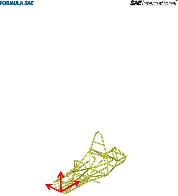
Directions – The following coordinate system and labeling convention is used within these rules
o Longitudinal (X) o Transverse (Y) o Vertical (Z)
|
Z |
|
Y |
|
X |
AF4 |
Structural Requirements |
AF4.1 |
Main Roll Hoop, Bracing and Bracing Supports |
AF4.1.1 |
Load Applied: Fx = 6.0 kN, Fy=5.0 kN, Fz=-9.0 kN |
AF4.1.2 Application point: Top of Main Roll Hoop
AF4.1.3 Boundary Condition: Fixed displacement (x,y,z) but not rotation of the bottom nodes of both sides of the front and main roll hoops.
AF4.1.4 Max Allowable Deflection: 25mm
|
73 |
© 2011 SAE International. All Rights Reserved |
2012 Formula SAE Rules |

AF4.1.5 Failure must not occur anywhere in structure
AF4.2 Front Roll Hoop
AF4.2.1 Load Applied: Fx = 6.0 kN, Fy=5.0 kN, Fz=-9.0 kN
AF4.2.2 Application point: Top of Front Roll Hoop
AF4.2.3 Boundary Condition: Fixed displacement (x,y,z) but not rotation of the bottom nodes of both sides of the front and main roll hoops.
AF4.2.4 Max Allowable Deflection: 25mm
AF4.2.5 Failure must not occur anywhere in structure
AF4.3 Side Impact
AF4.3.1 Load Applied: Fx = 0 kN, Fy=7 kN, Fz 0 kN. Vector direction of lateral load to be in toward the driver.
AF4.3.2 Application point: All structural locations between front roll hoop and main roll hoop in the side impact zone defined in B2.1. The analysis may show worst case only but need to support choice of location to justify why it is worst.
AF4.3.3 Boundary Condition: Fixed displacement (x,y,z) but not rotation of the bottom nodes of both sides of the front and main roll hoops.
AF4.3.4 Max Allowable Deflection: 25 mm
AF4.3.5 Failure must not occur anywhere in structure
AF4.4 Front Bulkhead & Bulkhead Support
AF4.4.1 Load Applied: Fx = 150 kN, Fy=0 kN, Fz 0 kN.
AF4.4.2 Application point: use the actual attachment points between the impact attenuator and the front bulkhead
AF4.4.3 Boundary Condition: Fixed displacement (x,y,z) but not rotation of the bottom nodes of both sides of the main roll hoop and both locations where the main hoop and shoulder harness tube connect. Monocoques should use both sides of the bottom of the main hoop and both sides of the upper attachment point between the main hoop and monocoque.
AF4.4.4 Max Allowable Deflection: 25mm
AF4.4.5 Failure must not occur anywhere in structure
AF 4.5 Shoulder Harness Attachment
AF4.5.1 Load Applied: 13.2 kN at seat belt attachment angle per attachment point.
AF4.5.2 Application point: Both harness attachment points simultaneously
|
74 |
© 2011 SAE International. All Rights Reserved |
2012 Formula SAE Rules |

AF4.5.3 |
Boundary Condition: Fixed displacement (x,y,z) but not rotation of the bottom nodes of both sides of |
|
|
the front and main roll hoops. |
|
AF4.5.4 |
Max Allowable Deflection: 25mm |
|
AF4.5.5 |
Failure must not occur anywhere in structure |
|
AF 4.6 |
Lap & Anti-Submarine AF Harness Attachment |
|
AF4.6.1 |
Load Applied: The loads specified in the monocoque harness attachment rules should be used on |
|
|
each att AF achment point. |
|
AF4.6.2 |
Application point: All harness attachment points simultaneously (same load case) |
|
AF4.6.3 |
Boundary Condition: Fixed displacement (x,y,z) but not rotation of the bottom nodes of both sides of |
|
|
the front and main roll hoops. |
|
AF4.6.4 |
Max Allowable Deflection: 25mm |
|
AF4.6.5 |
Failure must not occur anywhere in structure |
|
AF4.7 |
Front Bulkhead & Bulkhead Support Off Axis |
|
AF4.7.1 |
Load Applied: Fx = 149 kN, Fy=17.25 kN, Fz 0 kN. |
|
AF4.7.2 |
Application point: Create load application node in the front bulkhead plane at the center of the front |
|
|
bulkhead. Load application node may be rigidly connected to the front bulkhead and impact |
|
|
attenuator attachment points. |
|
AF4.7.3 |
Boundary Condition: Fixed displacement (x,y,z) but not rotation of the bottom nodes of both sides of |
|
|
the main roll hoop and both locations where the main hoop and shoulder harness tube connect. |
|
|
Monocoques should use both sides of the bottom of the main hoop and both sides of the upper |
|
|
attachment point between the main hoop and monocoque. |
|
AF4.7.4 |
Max Allowable Deflection: 25mm |
|
AF4.7.5 |
Failure must not occur anywhere in structure |
|
AF5 |
General Analysis Requirements |
|
|
The following requirements apply to the submitted structural certification process. |
|
AF5.1 |
Good analysis practice must be used and all assumptions and modeling approximations are subject to |
|
|
approval during the SRC process. This includes but is not limited to mechanical properties, mesh size |
|
|
and mesh quality. |
|
AF5.2 |
A Nastran analysis deck must be submitted electronically with the SRCF and supporting |
|
|
documentation. Nastran does not have to be used for the analysis, but is the required format for the |
|
|
organizer's to review the analysis input decks. |
|
AF5.3 |
Tubes with wall thickness less than 1.25 mm (0.049 inches) cannot be included in the analysis |
|
AF5.4 |
Holes in tubes may be neglected from the overall frame/monocoque model global results. However |
|
|
for each load case, the force and moments at both sides of the tubes need to be applied to a shell or |
|
|
75 |
|
© 2011 SAE International. All Rights Reserved |
2012 Formula SAE Rules |
|
|
solid model of the tube with the hole or cutout geometry modeled. The tube around the holes and |
|
cutouts may not show failure. |
AF5.5 |
Offsets between tubes at nodes need a detailed analysis similar to 5.3 where the actual connection is |
|
modeled using the end constraints from the overall vehicle model. Shell or solid models must be |
|
used. |
AF5.6 |
The following alternative boundary condition is acceptable for all structural requirements. The |
|
alternative is to not include the nodal constraints and instead run the model with inertia relief. In this |
|
case the mass distribution of the vehicle must closely approximate the actual intended mass |
|
distribution. Evidence must be provided supporting the mass distribution used in the model. A driver |
|
mass of 77 kg and a minimum vehicle mass of 300 kg must be used, even if these differ from the team's |
|
predicted vehicle mass. |
AF6 |
Intrusion Prevention |
|
Since the exact configuration of the tubes is not specified this rule is intended to limit the size of |
|
object which can intrude into the driver’s cell. |
AF6.1 |
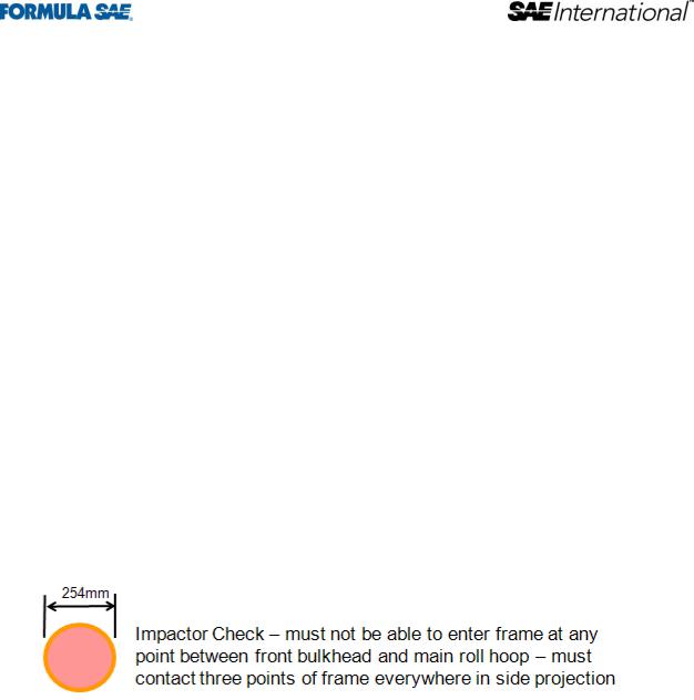
An impactor is defined as a circular disk with diameter of 254 mm (10 inches). The thickness is not |
|
relevant, but will generally be arounbd 2mm (0.080 inches) for the inspection process. |
AF6.1 |
The primary structure between the front bulkhead and main roll hoop must not allow the impactor to |
|
enter the primary structure. |
AF6.2 |
Anywhere on the structure where the impactor is attempted to be passed through the impactor must |
|
contact the structure in at least three points. This is not a projection requirement but a full 3- |
|
dimenaional requirement. |
|
76 |
© 2011 SAE International. All Rights Reserved |
2012 Formula SAE Rules |
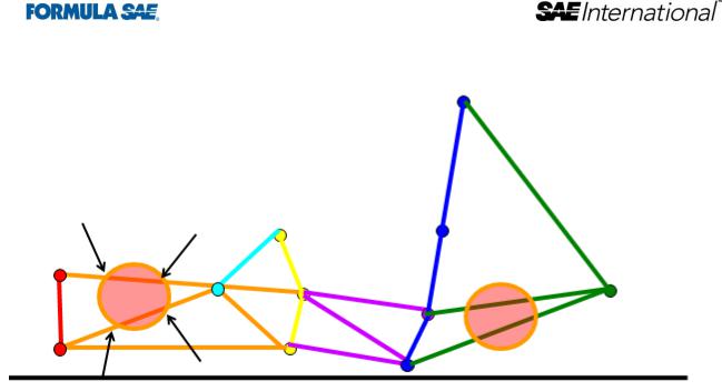
AF6.2 |
The impactor is a 3-dimensional requirement. It applies to all faces of the structure, including the |
|
|
front, sides, top, floor and rear, excluding only the cockpit opening specified in B4.1. If the driver is |
|
|
seated fully in front of the main hoop then the requirement does not apply behind the main hoop. If |
|
|
the driver is seated partially or fully behind the main hoop then the requirement extends to the end of |
|
|
the main hoop braces. |
|
AF7 |
Non-Applicable Rules |
|
|
The following rules are not applicable when building a frame to this alternative rule set. |
|
AF7.1 |
B3.10.4 In the side view of the vehicle, the portion of the Main Roll Hoop that lies above its |
|
|
attachment point to the Major Structure of the Frame must be within ten degrees (10°) of the vertical. |
|
AF7.2 |
B3.11.6 In side view, no part of the Front Hoop can be inclined at more than twenty degrees (20°) |
|
|
from the vertical. |
|
AF7.3 |
B3.12.3 In the side view of the Frame, the Main Hoop and the Main Hoop braces must not lie on the |
|
|
same side of the vertical line through the top of the Main Hoop, i.e. if the Main Hoop leans forward, |
|
|
the braces must be forward of the Main Hoop, and if the Main Hoop leans rearward, the braces must |
|
|
be rearward of the Main Hoop. |
|
AF7.4 |
B3.12.4 The Main Hoop braces must be attached as near as possible to the top of the Main Hoop but |
|
|
not more than 160 mm (6.3 in) below the top-most surface of the Main Hoop. The included angle |
|
|
formed by the Main Hoop and the Main Hoop braces must be at least thirty degrees (30°). See Figure |
|
|
3. |
|
AF7.5 |
B3.12.6 The attachment of the Main Hoop braces must be capable of transmitting all loads from the |
|
|
Main Hoop into the Major Structure of the Frame without failing. From the lower end of the braces |
|
|
there must be a properly triangulated structure back to the lowest part of the Main Hoop and the node |
|
|
at which the upper side impact tube meets the Main Hoop. This structure must meet the minimum |
|
|
requirements for Main Hoop Bracing Supports (see Rule B.3.3) or an SES approved alternative. |
|
|
Bracing loads must not be fed solely into the engine, transmission or differential, or through |
|
|
suspension components. |
|
|
|
77 |
© 2011 SAE International. All Rights Reserved |
2012 Formula SAE Rules |
|

AF7.6 B3.13.4 The Front Hoop braces must be attached as near as possible to the top of the Front Hoop but not more than 50.8 mm (2 in) below the top-most surface of the Front Hoop. See Figure 3.
AF7.7 B3.13.5 If the Front Hoop leans rearwards by more than ten degrees (10°) from the vertical, it must be supported by additional bracing to the rear. This bracing must be constructed of material per Rule B.3.3.1.
AF7.8 B3.19.1 The Front Bulkhead must be securely integrated into the Frame.
AF7.9 B3.19.2 The Front Bulkhead must be supported back to the Front Roll Hoop by a minimum of three
(3) Frame Members on each side of the vehicle with one at the top (within 50.8 mm (2 inches) of its top-most surface), one (1) at the bottom, and one (1) as a diagonal brace to provide triangulation.
AF7.10 B3.19.3 The triangulation must be node-to-node, with triangles being formed by the Front Bulkhead, the diagonal and one of the other two required Front Bulkhead Support Frame Members.
AF7.11 B3.24.4 With proper gusseting and/or triangulation, it is permissible to fabricate the Side Impact Structural members from more than one piece of tubing.
|
78 |
© 2011 SAE International. All Rights Reserved |
2012 Formula SAE Rules |

APPENDIX B-1 STRUCTURAL EQUIVALENCY SPREADSHEET
Appendix B-1 is posted at www.fsaeonline.com.
APPENDIX B-2 IMPACT ATTENUATOR DATA REPORT
Appendix B-2 is posted at www.fsaeonline.com.
|
79 |
© 2011 SAE International. All Rights Reserved |
2012 Formula SAE Rules |

2011 FORMULA SAE
PART C – STATIC EVENT REGULATIONS
ARTICLE 1: STATIC EVENTS AND MAXIMUM SCORES
The maximum possible scores in the static events are:
Technical Inspection |
No Points |
Cost and Manufacturing |
100 Points |
Presentation |
75 Points |
Design |
150 Points |
Total |
325 Points |
ARTICLE 2: TECHNICAL INSPECTION
C2.1 Objective of Technical Inspection
The objective of technical inspection is to determine if the vehicle meets the FSAE Rules requirements and restrictions and if, considered as a whole, it satisfies the intent of the Rules.
C2.1.1 For purposes of interpretation and inspection the violation of the intent of a rule is considered a violation of the rule itself. (See Rule A3.6)
C2.1.2 Technical inspection is a non-scored activity.
C2.2 Inspection & Testing Requirement
Each vehicle must pass all parts of technical inspection and testing, and bear the inspection stickers, before it is permitted to participate in any dynamic event or to run on the practice track.
C2.2.1 All items on the Inspection Form must be clearly visible to the technical inspectors.
C2.2.2 Visible access can be provided by removing body panels or by providing removable access panels.
C2.3 Team Responsibility
Teams are responsible for confirming that their vehicle, and the required equipment, satisfies the requirements and restrictions of the FSAE Rules before presenting it for Technical Inspection.
C2.3.1 Presenting a vehicle for Technical Inspection constitutes a declaration by the team that they have determined by self inspection that the vehicle complies with the Rules.
C2.4 Items to be Inspected
The following items must be brought to Technical Inspection:
Vehicle
Technical Inspection Form
Dry and wet tires
Driver’s equipment - for all drivers including arm restraints, helmets, suits, gloves, eye protection, balaclavas, socks and shoes.
Fire extinguishers
Push bar
|
80 |
© 2011 SAE International. All Rights Reserved |
2012 Formula SAE Rules |