

Vertical Crater Retreat
Vertical Crater Retreat (VCR) applies to orebodies with steep dip and competent rock in both ore and host rock. Part of the blasted ore will remain in the stope over the production cycle, serving as temporary support.
VCR was originally developed by the Canadian mining company INCO, and uses the crater blasting technique of powerful explosives in large diameter holes. Concentrated spherical charges are used to excavate the ore in horizontal slices, from the stope bottom upwards. The ore gravitates to the stope floor draw points, and is removed by loaders. Each stope is cleaned out before CHF backfilling.
Development for VCR stoping consists of: a haulage drift along the orebody at the drawpoint level; drawpoint loading arrangement underneath the stope; an undercut; and an overcut access for drilling and charging.
The ore in a slope block is drilled from the overcut excavation using DTH rigs. Holes, mainly vertical, are drilled downward, breaking through into the undercut. Hole diameters vary from 140 to 165 mm, commonly spaced on a 4.0 m x 4.0 m grid.
From the overcut, powerful spherical charges are positioned by skilled crew in the lower section of the blast hole, at specified distances from the stope roof. The hole depth is measured, and it is stemmed at the correct height. Explosive charges are lowered down each hole and stemmed, usually to blast a 3.0 m slice of ore, which falls into the space below.
VCR charging is complex, and its techniques have to be mastered, in order to avoid damaging the surrounding rock.
Cut and Fill Stoping
Cut-and-fill mining is applied to mining steeply dipping orebodies, in strata with good to moderate stability, and a comparatively high-grade mineralization.
It provides better selectivity than SLOS and VCR mining, and preferred for orebodies with irregular shape and scattered mineralization where high grade sections can be mined separately, and low grade rock left in the stopes.
Cut-and-fill mining excavates the ore in horizontal slices, starting from bottom undercut, advancing upward .The ore is drilled, blasted, loaded an removed from the stope, which is then backfilled with deslimed sand tailings from the dressing plant, or waste rock carried in by LHD from development drives. The fill serves both to support stope walls, and as a working platform when mining the next slice.
Before filling, stope entries are barricaded and drainage tubes installed The stope is filled with sand to almost full height, and cement is mixed into the final pours, to provide a solid floor for mobile machines to operate.
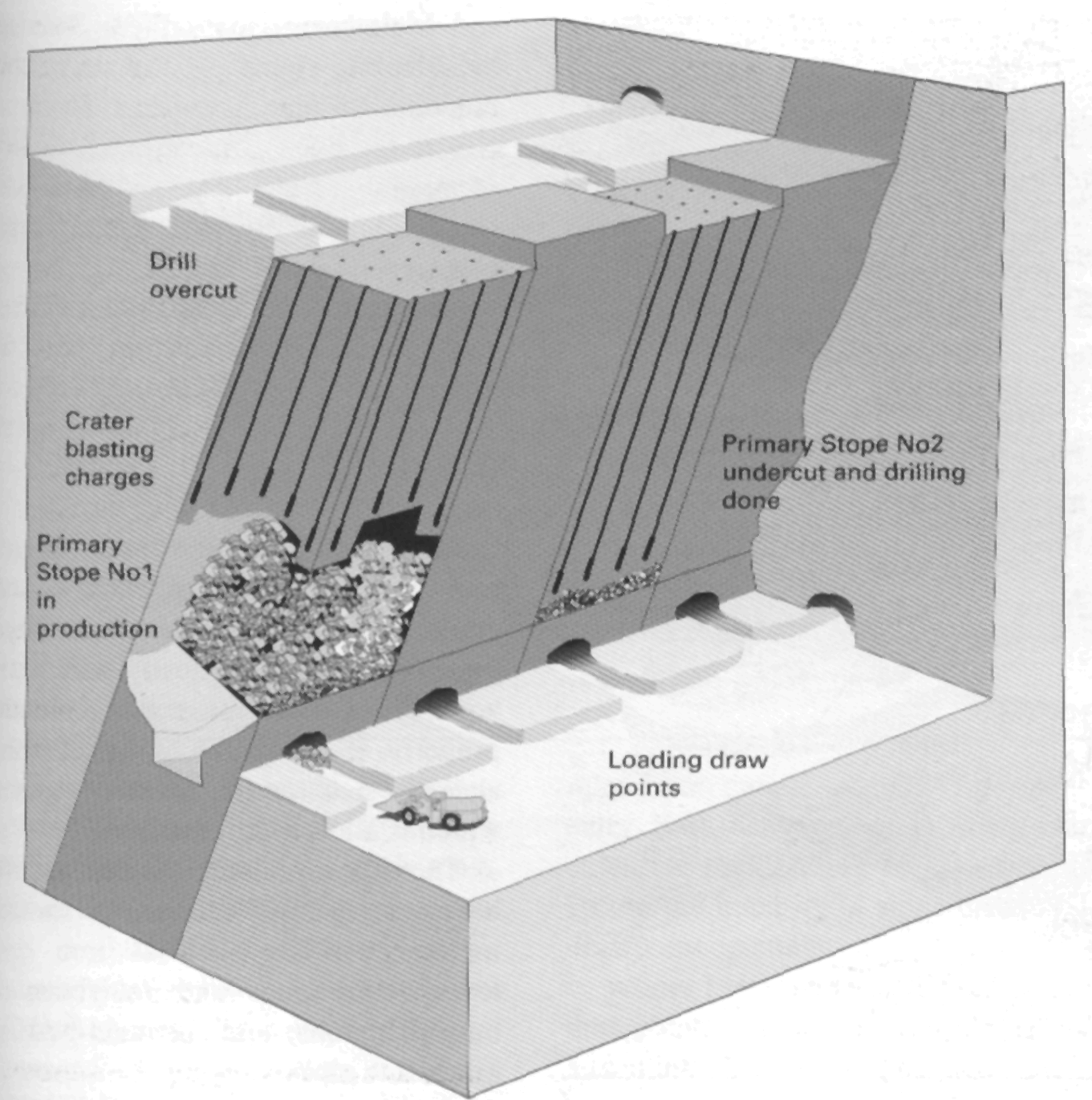
Figure 3. VCR primary stoping
Development for cut-and-fill mining includes: a footwall haulage drive along the orebody at the main level; and undercut of the stope area, with drains for water; a spiral ramp in the footwall. with access drive to the undercut; and a raise connection to the level above, for ventilation and filling material.
The stope face appears as a wall, with an open slot at the bottom, above the fill. Breasting holes are drilled by a rig. charged and blasted, with the slot underneath providing swell space for the blasted rock.
The mineralization shows in the stope face, where it can be inspected by geologists. The drill pattern can be modified, to follow variations in ore boundaries. Sections with low grade can be left in place, or deposited in adjacent mined-out stope sections. Mining can divert from planned slope boundaries, and recover enclosures of mineral from the host rock.
The smooth fill surface and controlled fragmentation are ideal for LHD loaders, the standard vehicle for mucking and transport in cut-and-fill mines. Tramming distances from stope to orepass must be within convenient range, and the orepass may be constructed within the stope using steel lining segments installed in advance of each sand layer.
There is a trend towards bench and stope, as at Mt Isa, Australia, and towards stope and paste fill, as at Zinkgruvan, Sweden.
Sublevel Caving
Sublevel caving (SLC) adapts to large orebodies. with sleep dip and continuity at depth. Sublevel footwall drills have to be stable, requiring occasional rockbolting only. The hangingwall has to fracture and collapse, following the cave, and subsidence of the ground surface above the orebody has to be tolerated.
Caving requires a rock mass where both orebody and host rock fracture under controlled conditions. As the mining removes rock without backfilling, the hanging wall keeps caving into the voids. Continued mining results in subsidence of the surface, where sinkholes may appear. Continuous caving is important, to avoid creation of cavities inside rock, where a sudden collapse could induce an inrush.
SLC extracts the ore through sub-levels, which are developed in the ore-body at regular vertical spacing. Each sublevel features a systematic layout with parallel drifts, along or across the orebody. In wide orebodies, sublevel drifts start from the footwall drive, and continue across to the hanging wall. In narrow orebodies, sublevel drifts branch off in both directions from a central crosscut drive.
Development to prepare SLC stopes is extensive, and mainly involves driving multiple headings to prepare sub-levels. A ramp connection is needed to connect different sublevels, and to communicate with main transport routes. Orepasses are also required, at strategic locations along sublevels, connecting to the main haulage level.
A section through the sublevel area will show drifts spread across the orebody, in a regular pattern, both in vertical and horizontal projections. The diamond shaped area, which can be traced above each drift, delineates the ore volume to be recovered from that drift.
Longhole rigs drill the ore section above the drift, in a fan-spread pattern, well ahead of production.
Blasting on each sublevel starts at the hanging wall, and mining retreats toward the footwall. Adjacent crosscuts are mined at a similar pace, with upper sublevels maintained ahead of lower sublevels. to preserve the cave and avoid undermining.
Each longhole fan is blasted separately, and the ore fills the drawpoint. Mucking out by LUD continues until the waste dilution reaches the set limit. The LHD then moves to a freshly blasted crosscut, while the charging team prepares the next fan for blasting.
Sublevels are designed with tramming distances matched to particular sizes of LIID-loaders. Mucking out is, like the other procedures in sublevel caving, very efficient. and the loader can be kept in continuous operation. Waste dilution in SLC varies between 15% and 40%, and ore losses may be 15% to 25%, depending on local conditions.
Dilution is of less influence for ore-bodies with diffuse boundaries, where the host rock contains low-grade minerals. Similar rules apply to magnetite ores, which are upgraded by simple magnetic separators. Sulphide ores, however, are refined by costly flotation processes, so dilution has to be closely controlled.
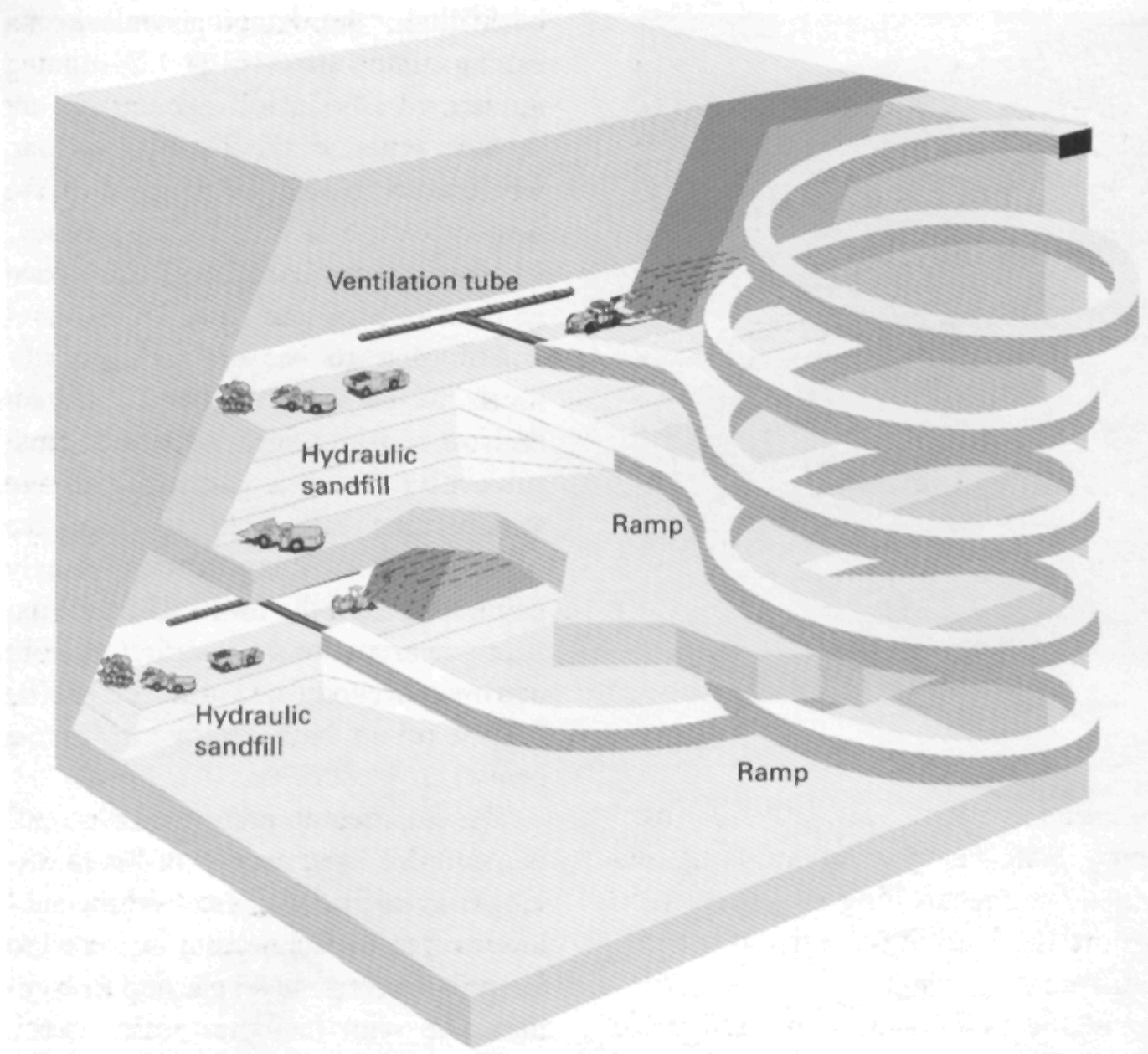
Figure 4. Cut-and-fill stope layout.
SLC is schematic, and repetitive, both in layout and working procedures. Development drifting, production drilling of long holes, charging, blasting and mucking out are all carried out separately, with work taking place at different levels simultaneously. There is always a place for the machines to work, making SLC a method which integrates mechanization into efficient ore production.
Block Caving
Block-caving is a large scale production mining method applicable to low' grade, massive orebodies with: large dimensions both vertically and horizontally; a rock mass that behaves properly, breaking into blocks of manageable size and a ground surface which is allowed to subside.
These rather unique conditions limit block-caving applications to special mineral deposits such as iron ore, low-grade copper and molybdenum mineralizations, and diamond-bearing kimberlite pipes.
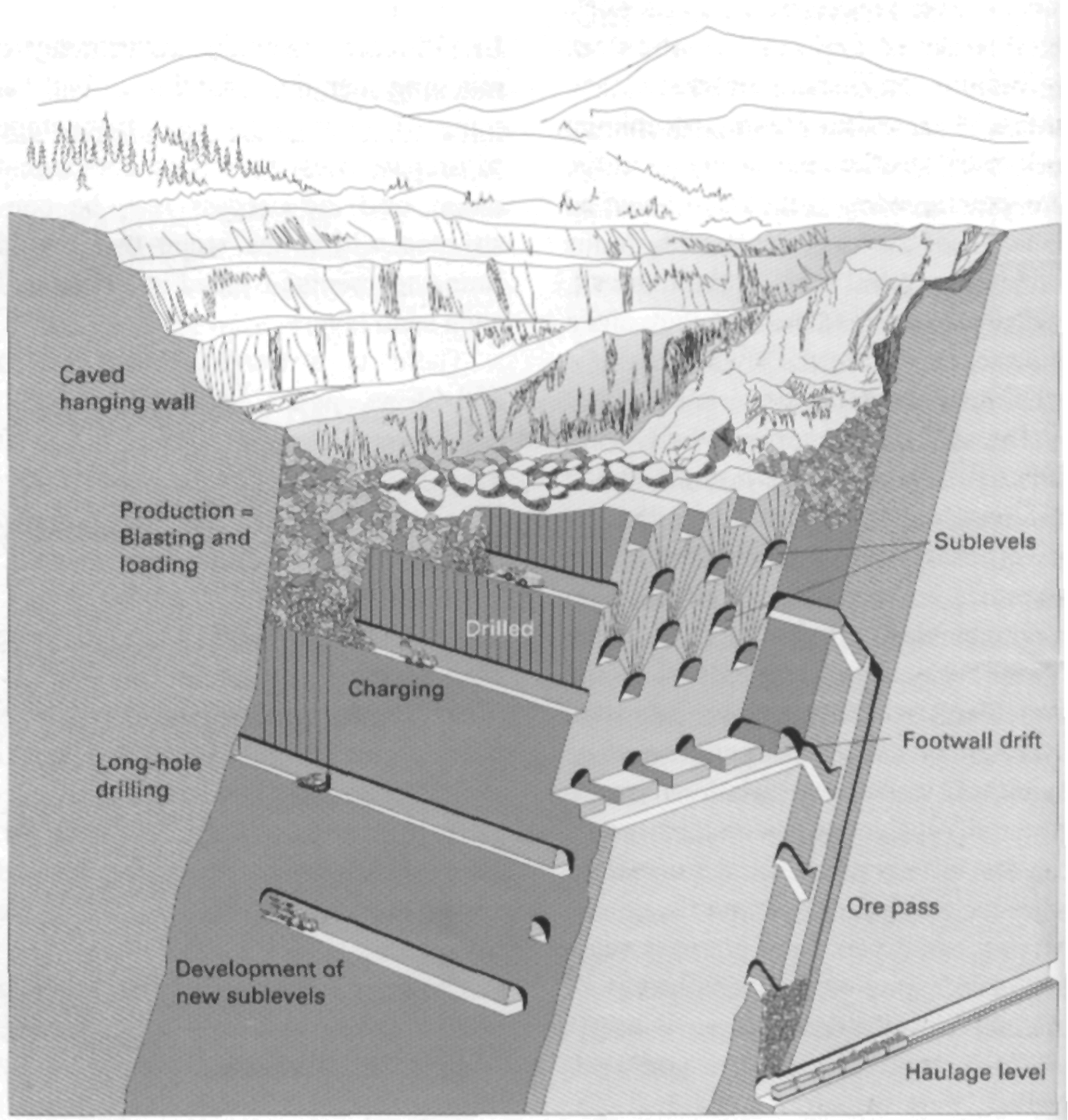
Figure 5. Sublevel caving lavout
Block caving is based on gravity combined with internal rock stresses, to fracture and break the rock mass. The drilling and blasting required for ore production is minimal, while development volume is huge. Blocks of orebody may have areas of several thousands of square metres. Caving is induced by undercutting the block by blasting, destroying its ability to support the overlying rock. Gravity forces, in the order of millions of tonnes, act to fracture the block. Continued pressure, and secondary blasting, break the rock into smaller pieces to pass the drawpoints, where the ore is handled by LHD-loaders or trains.
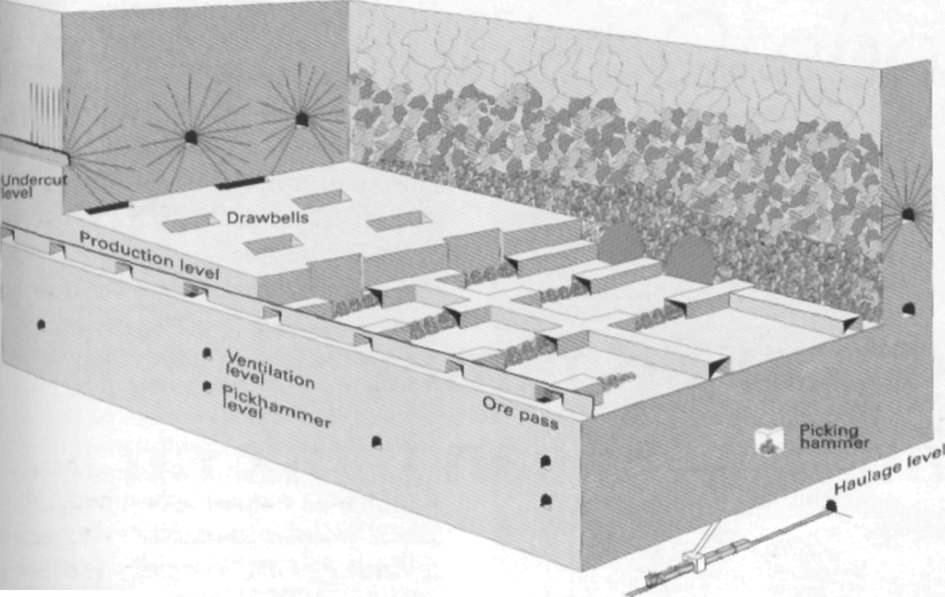
Figure 6. Block caving layout.
Development for block-caving applying conventional gravity flow requires an undercut, where the rock mass underneath the block is fractured by longhole blasting. Drawbells with finger raises are excavated beneath the undercut, to gather broken rock to the grizzly (picking hammer) level, where oversize boulders are caught, and broken by blasting or hydraulic hammer. A lower set of finger raises channels ore from the grizzlies to chutes for train loading on the main haulage level.
The intention is to maintain a steady draw from each block, and records are kept of volumes extracted from individual draw-points. It is often necessary to assist the rock mass fracturing, by longhole drilling and blasting in widely spaced patterns.
Drifts and other openings in the block caving area are excavated with minimum cross sections for man-entry. Still, heavy concrete lining and extensive rock bolting is necessary, to secure the integrity of mine drifts and drawpoint openings.
Where LHD loaders are used in the drawpoints, a ventilation level is added into development plans.
Shrinkage Stoping
In shrinkage stoping, traditionally a common mining method, ore is excavated in horizontal slices, starting from the stope bottom and advancing upwards. Part of the blasted ore is left in the stope, to serve as a working platform, and to give support to the stope walls.
Blasting swells the ore by about 50%, which means that a substantial amount has to be left in the stope until mining has reached the top section, following which final extraction can take place. Shrinkage stoping can be used for orebodies with: steep dips; comparatively stable ore and sidewall characteristics; regular ore boundaries; ore unaffected by storage (some sulphide ores oxidize, generating excessive heat).
The development consists of: haulage drift and crosscuts for mucking at stope bottom; establishment of drawpoints and undercut; and a raise from the haulage level passing through the undercut to the main level, providing access and ventilation to the working area.
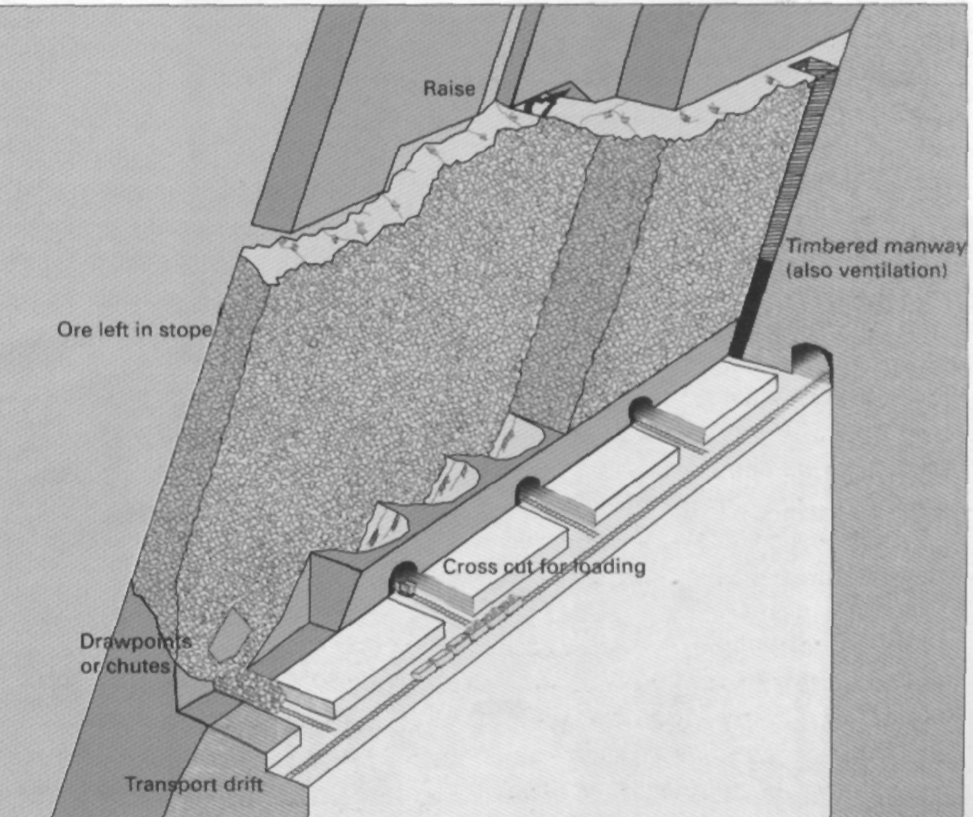
Figure 6. Shrinkage stoping layout
Drilling and blasting are carried out as overhead stoping. The rough pile of blasted ore prevents the usage of mechanized equipment, making the method labour-intensive.
List of words
hanging wall – висячий бік
footwall – підошва виробки
drift – штрек
dilution – розубоження (розубожування) корисних копалин
drilling rig – буровий станок
dip – падіння
angle of repose – кут природного схилу
pillar – цілик
сollar – отвір бурової свердловини, забурювати свердловину
drill pattern – сітка разміщення бурових свердловин
mucking – прибирання відбитоі породи
stope bottom – підошва виробки
toe spacing – відстань між забоями бурових свердловин
cut and fill stoping – шарова система розробки із закладкою виробленого простору
long hole stoping – очисне виймання с відбійкою руди глибокими свердловинами
sublevel stoping – підповерхова розробка , система підповерхових штреків
shrinkage stoping – система розробки з магазинуванням
sublevel caving – підповерхове обвалення
crosscut – квершлаг
overcut – верхній вруб
undercut – нижній вруб