

Linear Engine / L2V4bGlicmlzL2R0bC9kM18xL2FwYWNoZV9tZWRpYS80Nzg0
.pdfFigure 3.9. The average frequency is related directly to the operational period.
22
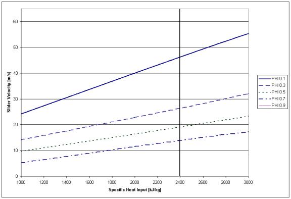
Figure 3.10. Slider mid-stroke velocity is seen to increase with an increase to the specific heat input.
From the numerical analysis it is possible to obtain the relationships for position, work output, in-cylinder pressure and velocity as a function of time and pressure as a function of cylinder volume. To show the effects of varying the bore and the mass of the slider on the operation of the engine, several simulations were performed calculating the above relationships. Table 3.2 lists the parameters that were held constant for each of the trails. Table 3.3 shows the test matrix values of the mass of the slider and the cylinder bore.
23
Table 3.2. Simulation constants.
Parameter |
Value |
||||
|
|
|
|
||
|
Qin |
1000 |
kJ |
|
|
|
|
|
kg |
||
|
m |
||||
|
|
||||
|
|
|
|
||
|
φ |
0.5 |
|
||
|
|
|
|||
|
xm |
0.0355 m |
|||
|
|
|
|
|
|
Table 3.3. Test trials mass and bore values.
Trial |
Slider Mass [kg] |
Cylinder Bore [mm] |
|
|
|
1 |
5 |
75 |
|
|
|
2 |
10 |
75 |
|
|
|
3 |
2.5 |
75 |
|
|
|
4 |
5 |
53 |
|
|
|
5 |
5 |
106 |
|
|
|
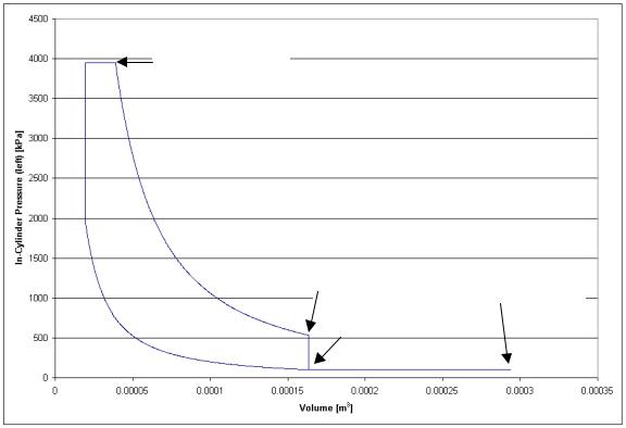
From the analysis plots of the position, work output, in-cylinder pressure and velocity versus time and the in-cylinder pressure versus volume were generated for the five trials. Plots of these relationships for trial 1 can be seen in Figures 3.11 to Figure 3.15. The other plots can be found in Appendix B. These plots were produced for the left cylinder in a left to right and back cycle except for Figure 3.12 which shows one left to right stroke. From the simulation, it was concluded that with an increase in the mass of the slider, the time to complete a stroke increases. The same is true for an increase in cylinder bore. From Figures 3.11 and 3.12 it can be seen that the velocity of the slider increases quickly then reaches a constant value and finally decreases quickly at the end of
24
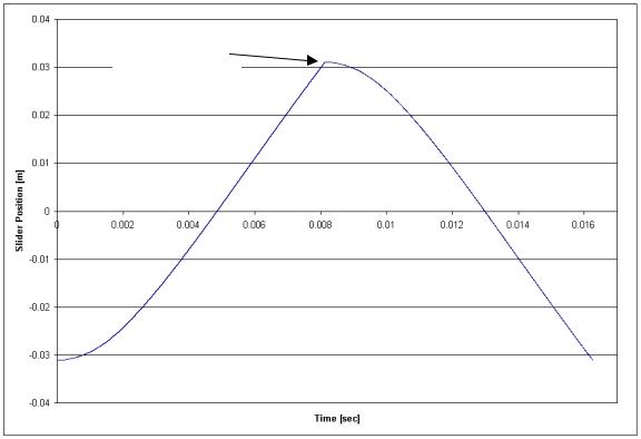
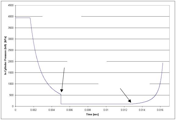
the stroke. The plot of the work output in time, Figure 3.13, shows positive work output during the expansion stroke and negative compression work during compression stroke. Finally, Figures 3.14 and 3.15 show the in-cylinder pressure traces for the simulated limited pressure cycle.
Motion Reversal
Figure 3.11. Slider position versus time shows near constant velocity over the majority of the stroke. The velocity ramps up to a near constant value and then drops to zero at the end of the stroke due to the heat input at constant volume. This can also be seen in Figure 3.12.
25
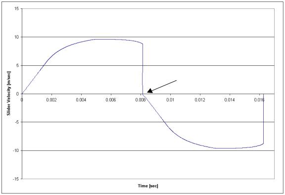
Motion Reversal
Figure 3.12. Slider Velocity versus time shows the velocity is near constant for most of the stroke.
26

Constant Pressure
Heat Addition End
Exhaust Port
Opened
Motion Reversal
Exhaust Port Closed
Figure 3.13. Work output versus time shows positive work being performed during the expansion stroke and negative work during the compression stroke. During the gas exchange operation when the exhaust port is open, work output can be seen to have offsetting positive and negative work regions.
27
Constant Pressure
 Heat Addition End
Exhaust Port
Opened
Exhaust Port Closed
Figure 3.14. In-cylinder pressure versus time
28
Constant Pressure
Heat Addition End
Exhaust Port
Opened |
Motion Reversal |
||
|
|
||
|
|
||
|
Exhaust Port Closed |
|
|
|
|
|
|
Figure 3.15. In-cylinder pressure versus in-cylinder volume shows a pressure trace of the idealized model.
29
4. Engine Prototype
4.1 Description
The Diesel prototype of 75 mm bore and 71 mm stroke was sized to use twostroke cycle personal watercraft (Kawasaki Jetski 300sx) components to reduce development time and cost. Cylinder heads were designed and fabricated that allowed for direct fuel injection and also provided water cooling to the Kawasaki cylinders. The pistons also were from the Kawasaki engine but were machined to remove the lower portion of the piston skirt. This was done to prevent the skirt from contacting the bottom end that was designed to allow the engine to be scavenged by in house compressed air. The pistons were directly connected by an aluminum rod that had provisions for mounting the moving portion of the position sensor and the translator magnets for the linear alternator. A simple I-beam frame provided support for the cylinders, alternator, and the stationary portion of the position sensor.
A single manually operated valve regulated air pressure to the engine. Lubrication to the engine was supplied through the intake air by means of in-line air-tool lubricators. These lubricators provided enough oil to the cylinder to preserve the integrity of the rings. Cooling water was forced into the bottom of the cylinder jackets and out through the heads from the house water supply. The alternator was used to provide the necessary motoring force for engine cranking. The engine control unit (ECU) controlled the alternator coils in motoring the engine and automatically disengaged them when the shaft speed exceeded a preset value, inferring that the engine had started. Because the stroke of the engine was not mechanically constrained and therefore allowed to vary during normal operation, optimal port location could vary with each cycle.
30
Another variable dependent on the stroke was the compression ratio, which had a theoretical maximum, for this particular engine of approximately 50:1. This was calculated with the knowledge of exhaust port locations, the dimensions of the cylinder, clearance volume and assuming that the motion is reversed exactly at the point of contact when the piston meets the head. The clearance volume was assumed to be the volume in the head, which allows access to the cylinder for the glow plugs and fuel injectors. A sketch of the major engine components is shown in Figure 4.1.
Fuel delivery was preformed by a common rail, direct injection system. The fuel injectors (Bosch part # B 445 110 130) were supplied by a high-pressure pump (Bosch part # B445 010 035-01) that maintained the common rail at a pressure controlled by the ECM, usually set to 9,000 psi. The high-pressure pump maintained the pressure through the use of a pulse width modulated regulator. Supplying the high-pressure pump was a automotive fuel pump (Master part # E2000) that was regulated at 38 psi. Fuel metering was pulse width modulated by the ECM and was manually adjusted by means of a potentiometer for each cylinder. The ECM allowed for the adjustment of the pulse width of injection and start of injection position for each cylinder and also the control of the rail pressure. To ensure ignition when the engine was cold or during cranking when compression was low, glow plugs (International part # 1820697C1) were fitted to the heads directly in the fuel injector spray path. The glow plugs were manually switched on or off . A dimensional sketch of the cylinder and head assembly is shown in Figure 4.2.
31