

Linear Engine / L2V4bGlicmlzL2R0bC9kM18xL2FwYWNoZV9tZWRpYS80Nzg0
.pdfThe current research involved an engine consisting of two pistons, connected solidly by a rod, such that the two pistons reciprocated with precisely the same motion. The motion of the piston is not mechanically prescribed but is rather a result of the balance of in-cylinder pressures, inertia forces, friction forces and the applied load. Idealized modeling of a two-stroke linear engine, assuming a limited pressure cycle of operation, has yielded a closed form solution for piston motion. A benchtop prototype of a linear engine was constructed and tested. The prototype was a direct injection, Diesel fueled compression ignition engine and was tested with varying degrees of success. At the time of this thesis the engine has cranked and fired briefly. However, sustained operation has not taken place due to failures in the engine controller upon firing.
There were several reasons as to why the development of this engine went to compression ignition over spark ignition. First, it could be seen from the past study that an increase in the compression ratio would reduce the amount of adverse work required to reverse the piston motion making more work available for generating power. With the higher compression ratio the piston would act as a gas spring reversing the piston motion. Next, this engine has been developed on the basis of efficiency. By using compression ignition, compression ratios higher than a spark ignited engine can be achieved and therefore higher thermal efficiency is possible. Operation without a throttle would also increase the overall efficiency of the engine. Finally, past development and testing had shown that throttled operation was undesirable.
2
2. Literature Review
Free piston engines have been investigated for many years. A study of literature and patents pertaining to this scrutiny has been presented in this chapter.
Achten [5] studied and documented the different types of free piston engines. His study concentrated on the conceptual differences between the different mechanisms.
Crankless gas generator piston engines were used in the 1950’s. These engines consisted of opposed pistons that were each directly connected to an air compressor piston. The mix of compressed air and engine exhaust was then sent to drive a gas turbine Cleveland Diesel Engine [6]. Frey et al. [7] built and tested a free piston gas generator turbine set that was sized for an automobile.
Galitello [8] patented a two-stroke cycle, variable compression, free piston engine. The engine consisted of two directly opposed identical, outward compressing pistons that were rigidly connected. Power was extracted from a central hydraulic cylinder or by a linear alternator. The engine was spark ignited and computer controlled. The computer control system sensed the desired power output, fuel combustion properties and energy generated from the fuel and would adjust the combustion accordingly. This allowed the engine to use a variety of fuels. The inventor claimed ultra high frequency operation hence no vibration.
Bock [9] presented a two-stroke cycle compression ignition engine pump combination. A central pump cylinder that was directly connected to the pistons extracted power. There were inlet and outlet valves as well as a common suction chamber in the central part of the engine. The engine had gas cushioning accomplished by a nitrogen filled elastic annular body. The gas cushioning served as a shock absorber
3
for the engine vibration. The engine also had oil cooling by means of cooling jackets around the cylinders.
Widener and Ingram [10] submitted a numerical model of a free piston linear generator for a hybrid vehicle modeling study. The model addressed the use of a free piston engine coupled with a linear generator as a potential auxiliary power unit in hybrid electric vehicles. The feasibility of such a model was analyzed with regards to power output and efficiency of the unit with reference to conversion of mechanical power output of the linear engine to electrical power output. The study was conducted on a twostroke cycle engine and a reciprocating rig developed to characterize the operation of the generator.
In the thesis of Goldsborough [11], a numerical simulation of a two-stroke cycle free piston engine was performed. This study concentrated on the analysis of homogenous charge compression ignition (HCCI) of hydrogen fuel. The author calculated the HCCI process to be near constant volume which enable the engine to operate on a very lean fuel-air charge. The study concluded that charge temperature at the port closure had the greatest effect on the achieved compression ratio, because it fixes the amount of compression heating needed for combustion to occur.
Past linear engine research at West Virginia University has included the construction and testing of a small bore gasoline, two-stroke cycle engine. The design consisted of two directly opposed identical pistons with a linear alternator in the center. The engine development had taken two concurrent paths. First was the design, construction, and testing of the prototype. Second was the fundamental analysis and numerical analysis of the engine. The engine was designed and constructed around
4
components of a commercially available chainsaw engine. The testing of the engine was performed under several loading conditions. It was found that under idle conditions the ignition timing had to be advanced to the point that spark occurred just after port closing to insure that the piston motion was reversed. This caused a large section of adverse work to be performed in reversing the piston, and a high coefficient of variance (COV) in the indicated mean effective pressure (iMEP). In a loaded highly, retarded timing case it was found that the adverse work was eliminated and the COV (iMEP) was reduced. This resulted in the engine operating more like a conventional internal combustion engine. The fundamental modeling of the engine lead to a closed form solution for the piston motion in dimensionless parameters. The numerical model of the engine then took the fundamental model and solved it in a dimensional form. The numerical model yielded theoretical in-cylinder pressure and displacement plots. From the different studies conducted it was determined that the design of a linear engine should be large bore and unthrottled, which would suggest a Diesel engine. The results of the research performed at West Virginia University have been published in several articles. These papers include Clark et al. [1, 2, 3], and Atkinson et al. [4].
Other significant patents include Allais [12], Deng et al. [13], Heintz [14], Iliev et al. [15], and Rittmaster et al. [16]. The different application of free piston engines and advantages of different mechanisms, applying to the reduction of components and cost and to the improvement of the engine efficiency were emphasized in these patents.
5
3. Fundamental Analysis
3.1 Introduction
The analysis presented below examines an ideal two-stroke engine with two opposed pistons connected solidly by a link rod and following the air-standard limitedpressure cycle of operation. A simple case of an idling engine or an engine from which power is extracted with constant force was examined. The air standard limited-pressure cycle of operation was assumed so as to provide pressures prevalent within the cylinders during idling operation of the engine. This created a fundamental analysis, that was useful in the study of the effects of heat input and the percent of heat input at constant volume.
It is understood that real systems are far more complex in comparison to the ideal case assumed in the following analysis and that a numerical analysis, similar to Atkinson et al. [4], might have to be employed in order to better understand the complex system. However, the fundamental analysis presented provides a basic understanding of the linear two-cylinder, internal combustion engine, much in the way an air-standard Otto cycle or Diesel cycle provides basic understanding of engine thermodynamic trends.
3.2 Engine Model
The ideal engine used in the analysis consisted of a linear two-cylinder two-stroke cycle internal combustion engine that follows an idealized limited-pressure cycle of operation. In reality, the cylinder pressures during scavenging will stray from the limitedpressure cycle, but this model was considered to be acceptable since major forces occurring during expansion and compression were properly incorporated. The engine consists of two opposed pistons connected by a rigid link rod. The pistons have equal and
6
symmetric strokes and are outward compressing. The engine was assumed to have instantaneous intake and exhaust blow down at the opening position of the ports and partial instantaneous heat release at the outermost position with the balance of the heat release occurring at constant pressure. Being a linear reciprocating engine, the piston does not encounter a top dead center position or a bottom dead center position, but rather
has an innermost (for the left piston; x = xs ) and outermost position (for the left piston;
x = −xs ). The analysis was carried out in a dimensional form on this idealized engine,
based on the assumption that an idling case of operation was in progress and the only load encountered was a frictional force. A better understanding of the model can be gained from the schematic presented in Figure 3.1. The maximum theoretical half stroke length of the piston is xm, while the maximum actual half stroke length of the piston is xs
as seen in Figure 3.2. The piston on a left to right stroke traverses from –xs to +xs. A
fundamental analysis was carried out by taking into consideration the heat added during one cycle, the intake pressures in the two cylinders, the friction force encountered by the pistons during their motion from the outermost position to the innermost position and the heat release ratio, that is, the percentage of the heat released at constant volume. The heat release ratio values were chosen to represent realistic engines with slider-crank mechanisms, while the ratio of specific heats was assumed to be constant. The analytical model permits a thorough understanding of the piston motion under various heat inputs and under different heat release ratios. It assists in developing a relation between the piston velocity, the piston position and the time required for one stroke.
7
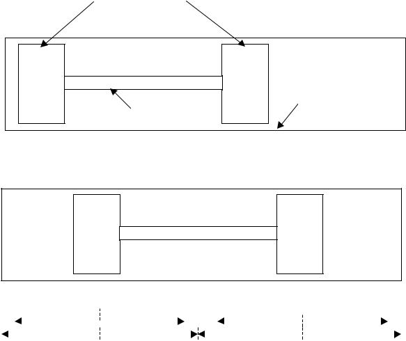
Pistons
Cylinder Wall
Link Rod
Figure 3.1. The ideal engine model at the beginning of a left to right compression stroke ( x = −xs ).
|
− xs |
|
+ xs |
|
|
|
|||
|
|
|
|
|
|
− xm |
|
+ xm |
|
|
|
x=0 |
||
|
− xs |
|
|
+ xs |
||
|
|
|
||||
|
|
|
|
|
|
|
|
− xm |
|
|
+ xm |
||
|
|
|
|
|||
|
|
|
x=0 |
|
||
|
|
|
|
|
|
|
Figure 3.2. The ideal engine model with the pistons at the midpoint position ( x = 0 ).
3.3 Assumptions
The numerical analysis was carried out on an ideal engine model using the following assumptions:
1.A two-stroke engine concept was assumed which follows an idealized limitedpressure cycle for its operation.
8

2.An idling case of operation with only a frictional force being encountered during the engine operation was assumed.
3.The heat input to the engine was used entirely for the work done to overcome the friction drag force acting on the piston (no heat loss).
The analysis was carried out on the idealized engine in a numerical form. Given these assumptions, a numerical solution in velocity versus position, velocity versus time and position versus time were obtained and are presented.
3.4 Dynamic Model
The model begins with a dynamic analysis of the engine. Consider the case of the engine in a left to right movement. The force balance of the system is:
P (x) |
πb2 |
− P (x) |
πb2 |
− F |
|
− m |
|
d 2 x |
= 0 |
4 |
4 |
|
s dt 2 |
||||||
l |
r |
|
f |
|
|
||||
where Pl is the left in-cylinder pressure, Pr is the right in-cylinder pressure, Ff is the frictional force applied to the engine, ms is the mass of the slider, b is the bore of the
engine, t is time, and x is the slider displacement. Both cylinder pressures are a function of the slider displacement. These two pressure terms can be combined into one pressure force term:
Fp (x) = [Pl (x)− Pr (x)]πb2
4
where Fp is the balance of the left and right cylinder pressures. The force balance for the
engine then becomes:
F |
|
(x)− F |
|
− m |
|
d 2 x |
= 0 . |
Equation (1). |
|
p |
f |
s dt 2 |
|||||||
|
|
|
|
|
|||||
9
3.5 Thermodynamic Model
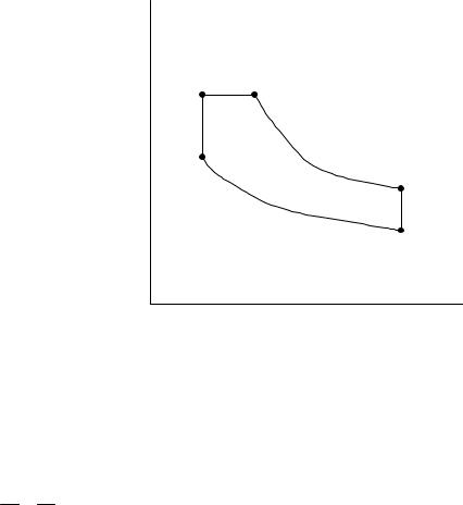
The thermodynamic analysis of the engine was performed to calculate the values of the variables that were based on the value of the heat input into the system. The engine model followed the air-standard limited-pressure cycle. The cycle consists of adiabatic compression from point 1 to 2, constant volume heat addition from 2 to 3, constant pressure heat addition from point 3 to a, adiabatic expansion from point a to 4, and constant volume blowdown from point 4 to 1. A schematic of the cycle can be seen in Figure 3.3.
3 a
4
2
1
Volume
Figure 3.3. Pressure volume diagram of limited-pressure cycle.
For this cycle there are two ratios that need to be defined. pressures during the constant volume heat addition, α
α= P3 = T3
P2 T2
First is the ratio of the
Equation (2).
Next is the ratio of the volumes during the constant pressure heat addition, β
10
β = |
Va |
= |
Ta |
Equation (3). |
|
|
V3 T3
Where T2, T3, and Ta are the average in-cylinder temperatures at the corresponding
points. These two ratios define how much of the heat input occurs at constant volume and how much occurs at constant pressure. The temperatures in the cylinders during the cycle can be defined as functions of the slider displacement and the intake temperature
Tin and f the percentage of the heat input that is at constant volume:
|
|
|
|
æ x |
m |
- x |
epr |
ön−1 |
|
|
|
|
|
|
|
|
||||||
T |
|
= T |
ç |
|
|
|
|
|
÷ |
|
|
|
|
|
|
|
Equation (4). |
|||||
2 |
|
|
|
|
|
|
|
|
|
|
|
|
|
|
|
|||||||
|
|
in ç |
xm |
|
- xs |
÷ |
|
|
|
|
|
|
|
|
||||||||
|
|
|
|
è |
|
|
ø |
|
|
|
|
|
|
|
|
|||||||
|
|
|
φQ |
|
|
|
|
æ xm - xepr ön−1 |
|
|
|
|
||||||||||
T |
|
= |
|
in |
|
+ T |
ç |
|
|
|
|
÷ |
|
|
|
|
|
Equation (5). |
||||
|
|
|
|
|
|
|
|
|
|
|
|
|
|
|||||||||
3 |
|
mCv |
|
|
|
in ç |
|
|
÷ |
|
|
|
|
|
|
|||||||
|
|
|
|
|
|
|
è |
|
xm - xs ø |
|
|
|
|
|
|
|||||||
|
|
|
(1 -φ )Q |
in |
|
|
|
φQ |
|
|
æ xm |
- xepr ön−1 |
|
|||||||||
T |
|
= |
|
|
|
|
|
|
+ |
|
in |
+ T |
ç |
|
|
|
÷ |
Equation (6). |
||||
a |
|
|
|
|
|
|
|
|
|
|
|
|
||||||||||
|
|
|
mC p |
|
|
|
|
|
mCv |
|
in ç |
xm |
÷ |
|
||||||||
|
|
|
|
|
|
|
|
|
|
|
è |
|
- xs ø |
|
||||||||
where xm is the maximum half stroke, xepr is the right exhaust port closing coordinate, Cv
and Cp are the specific heats for the working fluid, Qin is the total heat input into the
system, n is the ratio of the specific heats, and m is the mass of the air in the cylinder. The heat input is the sum of the constant volume heat input and the constant pressure heat input:
Qin = Cv (T3 -T2 )+ C p (Ta -T3 ) . |
Equation (7). |
The constant volume heat input is then:
Qincv = φQin . |
Equation (8). |
Thus the constant pressure heat input becomes:
Qincp = (1 -φ )Qin . |
Equation (9). |
f also defines a and b, such that:
11