

Cagle R.B. - Blueprint for Project Recovery[c] A Project Management Guide (2003)(en)
.pdf
256 |
B L U E P R I N T F O R P R O J E C T R E C O V E R Y |
difficult to create but always maintains the same relationships to other requirements.
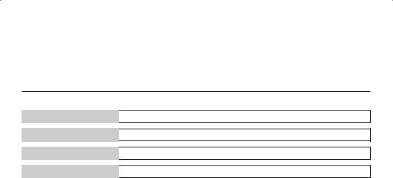
The matrix in Table A13-1 is a multipurpose matrix in that the Industry, Customer, and Enterprise Standards Documents are all included in one chart. You can use this technique or separate them into three different charts. The advantage of using three charts is that Industry and Enterprise charts will probably remain constant for most, if not all, projects and only the Customer Chart needs to be researched. The advantage of using the multipurpose chart is that the relationships between all elements—and there will be many—are clearly presented in one place.
Before the project starts, you should have a Standards Appearance Matrix already established for all the known standards and enterprise documents that drive the Project and Technical Plans. This is frequently a staff function and might appear in one of your enterprise policies. If it does not, build your own. There should be plenty of blank rows in the standard to work with. Use the blank rows to enter the requirements specific to your task. Your requirements document (contract) will drive the entries in the customer column. Ensure that every necessary standard is covered. In the sample matrix above, notice that, in the second entry, a customer document and an enterprise document are side- by-side. That’s because they are the same requirement. It is common for a company to absorb standard requirements for their areas of operation as standard policies within the company. If you use a multipurpose matrix and the standards are common, include them both on the same row. If any requirement exists in any column, ensure that it is covered.
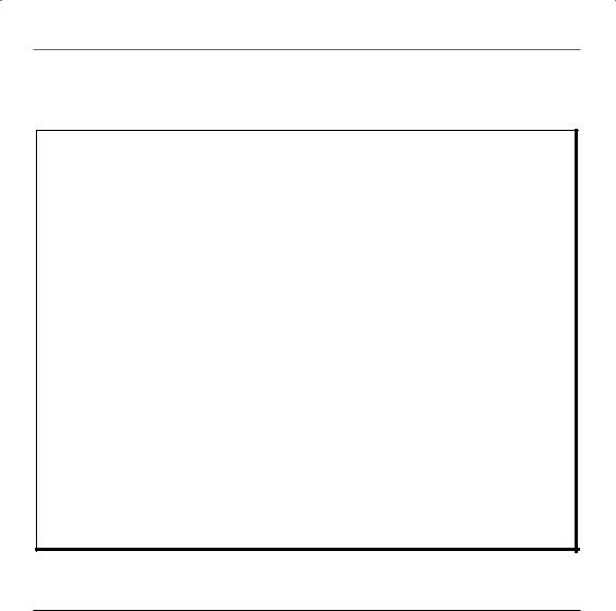
You can clearly see the relationship between the Enterprise Policies, Plans, and Processes and the various paragraphs of the Program/Project Plan in Figure A13-1. Further, the figure shows the relationship between Attachments and Appendices to the Program/Project Plan and the paragraphs of the Program/Project Plan as well as the Enterprise Policies, Plans, and Processes.
T a b l e A 1 3 - 1 — S t a n d a r d s T r a c e a b i l i t y M a t r i x
|
STANDARDS |
|
APPEARANCE |
||
Industry |
Customer |
|
Enterprise |
Project Plan |
Technical Plan |
ISO-9001 |
ISO-9001 |
|
Enterprise Quality |
Para 4.6.8 |
Part I, Para |
|
|
|
Policy 09350 |
|
4.5.6 |
|
MIL-STD-100 |
|
Enterprise Engineering |
N/A |
Part II, Para |
|
|
|
Standards 06050 |
|
1.2.3 |
|
|
|
|
|
|
|
|
|
|
|
|

S T A N D A R D S T R A C E A B I L I T Y M A T R I X |
257 |
F i g u r e A 1 3 - 1 — P o l i c y - t o - P r o g r a m P l a n t o S u p p o r t D o c u m e n t F l o w
|
Enterprise Policies, |
|
|
Attachs & |
|
Plans, & Processes |
|
Program Plan |
Appeds |
|
|
1 |
Introduction |
|
|
|
2 |
Scope |
|
|
|
2.1 |
Program Description |
|
|
|
2.2 |
Deliverables |
C |
|
|
|
||
|
|
2.3 |
Schedule |
18 |
|
|
|
||
|
M-M 04018 |
2.4 |
Sell-off Criteria |
27 |
|
|
|||
|
|
3 |
Reference Documents |
|
|
|
3.1 |
Contract |
|
|
|
3.2 |
Customer Documents |
|
|
|
4 |
Unusual Contract Clauses |
|
|
|
5 |
Responsibilities |
|
|
|
5.1 |
Organization, Staffing, and Responsibilities |
|
|
|
5.1.1 |
General |
|
|
M-M 05000 |
5.1.2 |
System Management |
|
|
M-M 06000 |
5.1.3 |
Subcontracts and Materials |
20 |
|
|
|||
|
M-M 04050 |
5.1.4 |
Data Management |
4 |
|
|
|||
|
M-M 04030 |
5.1.5 |
Configuration Management |
3 |
|
|
|||
|
M-M 07000 |
5.1.6 |
Quality Assurance |
14 |
|
|
|||
|
M-M 10050 |
5.1.7 |
Team Members and Alliances |
15 |
|
|
|||
|
M-M 11000 |
5.1.8 |
Training |
23 |
|
|
|||
|
|
|
|
|
This matrix should be built for the entirety of the Program/Project Plan and another should be constructed for the Technical Plan.
The symbol M-M refers to my company Modern-Management and is a part of the file database for all writings, workshops, and seminars. You need to enter your company policies, processes, etc., in this column.
I sincerely hope you are reading this Cause Description before your program starts rather than trying to recover from a problem. This is a time-consuming process, but is necessary for a smooth-running program.
If you have built your Project or Program plan according to the recommendations of this book, all but the left-most column will be apparent. It should then be a simple matter to insert your company plans into the left-most column.
If you have your own outline for a Project or Program Plan, you will need to start from scratch. The mechanics, however, are the same.
Once you receive your contract, you can begin referencing the elements of the contract to the outline of the Project Plan and the Technical Plan.


V E N D O R E V A L U A T I O N P R O C E S S |
259 |
an evaluation team with specialists in each of the areas to be evaluated (management, engineering, materials, quality, etc.). When the vendor’s proposals are received, begin the evaluation process.
Each specialty area—management, engineering, materials, quality, etc.— should have a sheet for each similar to the Vendor Evaluation Sheet shown in Figure A14-1 on page 260. The factors in each sheet will change with the specialty area and will be consistent with the overall evaluation scheme devised before the RFP/RFQ was issued and documented by the materials or subcontracts manager in a cover letter to all evaluators.
The materials or subcontracts manager will order and stack the Vendor Evaluation Forms as they come in and enter the results for each vendor in the Vendor Evaluation Summary Form as shown in Figure A14-2 on page 261.
Finally, the results from the Vendor Evaluation Summary Form will be transferred to the appropriate lines on the Vendor Selection Summary Score Sheet as in Figure A14-3 on page 262. The winner is determined from the Vendor Selection Summary Score Sheet.

V E N D O R E V A L U A T I O N P R O C E S S |
261 |
F i g u r e A 1 4 - 2 — V e n d o r E v a l u a t i o n S u m m a r y
VENDOR EVALUATION SUMMARY
Date
Program
Subcontractor/Vendor
Equipment/Software
Item |
|
Consideration |
Scale |
Rating* |
|
|
|
|
|
1 |
|
Technical |
0–25 |
10 |
|
|
|
|
|
2 |
|
Management |
0–5 |
2 |
|
|
|
|
|
3 |
|
Quality |
0–15 |
7 |
|
|
|
|
|
4 |
|
Procurement |
0–5 |
3 |
|
|
|
|
|
5 |
|
Financial |
0–10 |
5 |
|
|
|
|
|
6 |
|
Delivery |
0–20 |
10 |
|
|
|
|
|
7 |
|
Cost |
0–20 |
10 |
|
|
|
|
|
8 |
|
|
|
|
|
|
|
|
|
9 |
|
|
|
|
|
|
|
|
|
10 |
|
|
|
|
|
|
|
|
|
|
|
Subtotal |
|
47 |
|
|
|
|
|
|
|
No. of items rated |
|
7 |
|
|
|
|
|
|
|
Average of ratings (Subtotal/No of items) |
|
6.7 |
|
|
|
|
|
|
|
|
||
Current Quality Vendor survey on file? |
|
Yes |
||
|
|
|
|
|
D&B on file? |
|
|
Yes |
|
|
|
|
|
|
|
|
|
|
|
*From Vendor Evaluation Sheets

262 |
B L U E P R I N T |
F O R P R O J E C T R E C O V E R Y |
F i g u r e A 1 4 - 3 — V e n d o r S e l e c t i o n S u m m a r y S c o r e S h e e t |
||
|
|
|
|
VENDOR SELECTION SUMMARY SCORE SHEET |
|
SCORE SHEET FOR: |
* |
|
Date |
Item |
|
EVALUATION CONSIDERATIONS (POINT ALLOCATION 100) |
|
|
Vendor |
Name |
Score |
1. |
|
|
2. |
|
|
3.
4.
5.
Total (Sum of Points Given)
Score (Total/No. of Entries)
Comments:
Comments:
You should have a Vendor Evaluation Summary Score Sheet for each of the operating elements of the team (Engineering, Management, QA, etc.) and each of the factors of the procurement (cost, delivery, etc.). This form is the summary, by evaluator, of all the previous forms.
This form can be modified and used to evaluate subcontractor and vendor proposals. In that case, establish a ‘‘weighting’’ for each of the factors based on your program (e.g., Is technical more important than cost?)
*Operating element or factor, such as: Technical, Management, QA, Procurement, Cost, Delivery, etc.
M-M Form F-06013A

264 B L U E P R I N T F O R P R O J E C T R E C O V E R Y
F i g u r e A 1 5 - 1 — D e s i g n R e v i e w A p p r o v a l F o r m
DESIGN REVIEW APPROVAL
The ________(1)_____________ Design Review Minutes containing the ______(1)_________Design Review Package labeled _______(2)____________
and dated _____(3)________
and The _________(1)___________Design Review
conducted on _____(3)__________ together with the Design Review Action Items are hereby approved
therefore
__________(4)____________________ is hereby directed to proceed to the next stage of the program.
Signed _____(5)________ of __________(6)______________ Date _______________
Where:
(1)The Design Review—PDR, CDR, etc.
(2)Modification or issue
(3)Date of package or event
(4)The Contractor
(5)The Customer’s Representative
(6)The Contracting Authority