


Chapter 4: Interrupt Handling
bit is cleared, it was a phantom or ghost interrupt and the programmer should execute an interrupt return (the IRET instruction) to return to the interrupted program flow.
ISA card designers can avoid this problem by designing the card's IRQ output driver to remain tri-stated when not requesting service, allowing the pull-up resistor inside the 8259 to keep it high. The line is not prone to pick up noise spikes when it's high. When a request must be generated, the card drives the IRQ line low and then lets it go high again. This low-to-high transition registers as a request in the 8259. When the microprocessor generates the first interrupt acknowledge, the line is guaranteed to be high and the request is therefore valid.
Limited Number of IRQ Lines
In the ISA environment, IRQ lines are not shareable because only one transition is registered if more than one card generates a transition. The low-to-high transition generated by the first card is recognized by the interrupt controller and any subsequent transitions are ignored until the first request has been serviced. More than one ISA device may share an IRQ line as long as it is guaranteed that they never generate requests simultaneously. Since only one device may use each IRQ line, a fully-loaded machine may easily use up all of the available lines. An in-depth discussion of interrupt handling in the ISA environment may be found in the MindShare book entitled ISA System Architecture.
EISA Interrupt Handling
Shareable IRQ Lines
The interrupt controllers used in the EISA environment are a superset of the Intel 8259A controller. The 8259A allows the programmer to gang-program all eight IRQ inputs as either edge or level-triggered. In the EISA environment, machines must be capable of supporting both ISA and EISA-style cards. This means that the programmer must have the ability to individually select each IRQ input as either edge or level-triggered. The EISA interrupt controller has added an additional register for this purpose.
The ELCR, or Edge/Level Control Register, provides this selectivity. The master interrupt controller's ELCR is located at I/O address 04D0h, while the slave's is at I/O address 04D1h. Each of these registers is default programmed
35

EISA System Architecture
to edge-triggering upon power-up. Tables 4-1 and 4-2 illustrate their respective bit assignments.
|
|
|
|
Table 4-1. Master Interrupt Controller's ELCR Bit Assignment |
|
|
Bit |
|
|
Description |
|
|
|
|
|
|
|
|
7 |
|
|
0 = IRQ7 is edge-sensitive and non-shareable, 1 = IRQ7 is level-sensitive |
|
|
|
|
|
and shareable. |
|
|
6 |
|
|
0 = IRQ6 is edge-sensitive and non-shareable, 1 = IRQ6 is level-sensitive |
|
|
|
|
|
and shareable. |
|
|
5 |
|
|
0 = IRQ5 is edge-sensitive and non-shareable, 1 = IRQ5 is level-sensitive |
|
|
|
|
|
and shareable. |
|
|
4 |
|
|
0 = IRQ4 is edge-sensitive and non-shareable, 1 = IRQ4 is level-sensitive |
|
|
|
|
|
and shareable. |
|
|
3 |
|
|
0 = IRQ3 is edge-sensitive and non-shareable, 1 = IRQ3 is level-sensitive |
|
|
|
|
|
and shareable. |
|
|
2 |
|
|
always 0 because the master's IRQ2 input is used to cascade the slave |
|
|
|
|
|
interrupt controller’s output through the master. |
|
|
1 |
|
|
IRQ1 is dedicated to the interrupt request output of the keyboard inter- |
|
|
|
|
|
face. This bit must be 0, selecting edge-sensitive and non-shareable. |
|
|
0 |
|
|
IRQ0 is dedicated to the interrupt request output of the system timer. |
|
|
|
|
|
This bit must be 0, selecting edge-sensitive and non-shareable. |
|
36

|
|
|
|
|
Chapter 4: Interrupt Handling |
||
|
|
|
|
|
|
|
|
|
|
|
|
|
Table 4-2. Slave Interrupt Controller's ELCR Bit Assignment |
||
|
|
Bit |
|
|
Description |
|
|
|
|
|
|
|
|
|
|
|
7 |
|
|
0 = IRQ15 is edge-sensitive and non-shareable, 1 = IRQ15 is level- |
|
||
|
|
|
|
|
sensitive and shareable. |
|
|
|
6 |
|
|
0 = IRQ14 is edge-sensitive and non-shareable, 1 = IRQ14 is level- |
|
||
|
|
|
|
|
sensitive and shareable. |
|
|
|
5 |
|
|
IRQ13 is dedicated to the error output of the numeric coprocessor. This |
|
||
|
|
|
|
|
bit must be 0, selecting edge-sensitive and non-shareable. In reality, |
|
|
|
|
|
|
|
IRQ13 is shared by the numeric coprocessor and the chaining interrupt |
|
|
|
|
|
|
|
output of the DMA controller. More information regarding chaining can |
|
|
|
|
|
|
|
be found in the chapter entitled “EISA DMA.” |
|
|
|
4 |
|
|
0 = IRQ12 is edge-sensitive and non-shareable, 1 = IRQ12 is level- |
|
||
|
|
|
|
|
sensitive and shareable. |
|
|
|
3 |
|
|
0 = IRQ11 is edge-sensitive and non-shareable, 1 = IRQ11 is level- |
|
||
|
|
|
|
|
sensitive and shareable. |
|
|
|
2 |
|
|
0 = IRQ10 is edge-sensitive and non-shareable, 1 = IRQ10 is level- |
|
||
|
|
|
|
|
sensitive and shareable. |
|
|
|
1 |
|
|
0 = IRQ9 is edge-sensitive and non-shareable, 1 = IRQ9 is level-sensitive |
|
||
|
|
|
|
|
and shareable. |
|
|
|
0 |
|
|
IRQ8 is dedicated to the alarm output of the Real-Time Clock chip. This |
|
||
|
|
|
|
|
bit must be 0, selecting edge-sensitive and non-shareable. |
|
|
When programmed to recognize level-sensitive interrupt requests, the interrupt controller recognizes a low on an IRQ line as a request and the interrupt request line may be shared by two or more devices. The following paragraphs define how this works.
During the POST, software scans the area of memory space set aside for device ROMs, typically C0000h – DFFFFh, to determine if any expansion cards have device ROMs. When a device ROM is detected, the POST jumps to the initialization routine in the ROM to execute the card's POST and to install the start addresses of its interrupt service and BIOS routines into the proper entries in the interrupt table in memory. The ROM's initialization routine reads the current pointer from the interrupt table entry, saves it and writes the pointer to the device ROM's interrupt service routine in its place. After testing and initializing the card, the ROM code performs a return to the system POST. The POST then continues to scan the device ROM memory area for other device ROMs. If any are found, the same process is repeated. When another card is using the same IRQ line, its ROM code reads the current pointer from the interrupt table entry and saves it. This pointer points to the interrupt service routine within a previously detected device ROM for another EISA I/O card that is sharing this IRQ
37

EISA System Architecture
line. The second card's ROM code then stores a pointer to its own interrupt service routine into the IRQ line's assigned interrupt table entry. In this way, a linked list of interrupt service routine start addresses is created. Any loadabledevice drivers or TSRs that use shareable interrupt request lines should do the same.
Each shareable interrupt request line has a pull-up resistor on it (internal to the EISA interrupt controller). When no request is being generated, or when no I/O devices are physically connected to the line, the line is pulled-up to a high level. This provides a good deal of noise immunity on the line, preventing spurious requests.
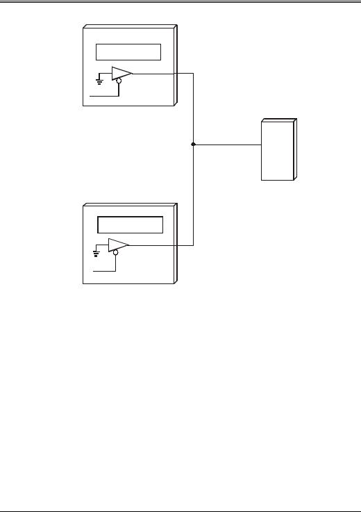
Figure 4-1 illustrates how multiple EISA I/O cards can share the same IRQ line. An I/O device that places a low on an interrupt request line when it generates a request may share the line with other devices that use it the same way. When a board of this type must generate a request, it acts as follows:
•Through an open-collector driver, it creates a path to ground. This places a low on the 8259's request input. If other I/O devices are sharing the line and generate requests simultaneously, the shared IRQ line is low.
•When an I/O board generates a request, it should also set its interrupt pending bit in a pre-defined I/O port on the card.
38
Chapter 4: Interrupt Handling
EISA I/O Card
Interrupt Pending
1
IRQ#
IRQn# Interrupt
Controller
Interrupt Pending
1
IRQ#
EISA I/O Card
Figure 4-1. IRQ Line Sharing
When the 8259 senses a low on a shareable request input, it generates an interrupt request to the microprocessor. When the microprocessor requests the interrupt vector, the 8259 responds with the vector for the line currently being serviced. The microprocessor then jumps to the interrupt service routine for the last device ROM detected during the POST. In this routine, an I/O read is performed from the card's interrupt pending register to determine if this card is generating a request. If the card's interrupt pending bit is set, the program continues and executes the remainder of the card's interrupt service routine to service the request. If the card's interrupt pending bit isn't set, however, the program jumps to the next interrupt service routine in the chain. The second service routine then polls its respective card's interrupt pending register to determine if it is generating a request. The act of servicing the request (for example, sending a character to a serial port) causes the requesting board's interrupt
39