


Chapter 2: EISA Bus Structure Overview
Chapter 2
The Previous Chapter
The previous chapter provided an overview of the features and benefits realized in the EISA environment.
This Chapter
This chapter introduces the EISA bus structure and its relationship to the system board and expansion cards. The concepts of master and slave are introduced and defined. The types of bus masters and slaves are identified.
The Next Chapter
The next chapter, “EISA Bus Arbitration,” describes the bus arbitration mechanism implemented in all EISA systems.
Community of Processors
The signals provided on each EISA expansion connector can be divided into four basic categories:
•Address bus group
•Control bus group
•Data bus group
•Bus arbitration group
Three of these four signal groups are present on the expansion slots found in IBM PC/XT/AT products and compatible computers. In EISA, the bus arbitration group has been added.
The EISA specification defines the signals found on the expansion connectors, as well as the permissible bus cycle types that can be performed by bus masters and the software protocol that bus masters must use when communicating with each other. It also defines the support logic residing on the system board
15

EISA System Architecture
and expansion cards that is necessary to support EISA capabilities. Examples would be the system board's Central Arbitration Control (CAC) and the data bus steering logic, which are discussed in subsequent sections.
Limitations of ISA Bus Master Support
The IBM PC XT/AT and compatible products are essentially single-processor systems. They have one microprocessor located on the system board that uses the address, control and data buses to communicate with the various memory and I/O devices found in a system.
The microprocessor on the system board is the bus master most of the time in a PC/XT/AT. It uses the bus to fetch instructions and to communicate with memory and I/O devices when instructed to do so by the currently executing instruction.
Upon occasion, however, devices other than the microprocessor require the use of the bus in order to communicate with other devices in the system. These devices are the DMA controller and the RAM refresh logic. The DMA controller must use the bus to transfer data between I/O devices and memory. The refresh logic must use the bus periodically to refresh the information stored in DRAM memory.
When a device other than the microprocessor (such as the DMA controller or the refresh logic) requires the use of the bus, it must force the microprocessor to give up control of the bus. This is accomplished by asserting the microprocessor's HOLD (Hold Request) input. Upon detecting HOLD asserted, the microprocessor electrically disconnects itself from the address, control and data buses so the requesting device can use them to communicate with other devices. This is called “floating” the bus. The microprocessor then asserts its HLDA (Hold Acknowledge) output, informing the requesting device that it has yielded the bus, making it the new bus master. The device remains bus master as long as it keeps the microprocessor's HOLD input asserted.
When a bus master other than the microprocessor on the system board has completed using the bus, it deasserts the microprocessor's HOLD input, allowing the microprocessor to re-connect itself to the bus and to become bus master again.
Although it is possible for an expansion card inserted into an IBM PC/XT/AT expansion slot to become bus master, there is a major drawback. When an expansion card becomes bus master in a PC/XT/AT, it can remain bus master as
16

Chapter 2: EISA Bus Structure Overview
long as it keeps the microprocessor's HOLD line asserted. There are no safety mechanisms built into a PC/XT/AT to prevent a bus master card from monopolizing the use of the bus to the exclusion of the microprocessor and the RAM refresh logic on the system board and potential bus master cards installed in other expansion connectors.
If, due to poor design or a failure, a bus master expansion card monopolizes the bus for an inordinate amount of time, the main microprocessor cannot continue to fetch and execute instructions. This could have serious consequences. In addition, the refresh logic is unable to become bus master on a timely basis and data in DRAM memory could be lost. Finally, other bus master cards are not able to become bus master and transfer data. To summarize, severe problems can be incurred when bus master expansion cards are used in a PC/XT/AT.
EISA Bus Master Support
The ISA bus mastering problem is fixed in the EISA environment by the addition of the EISA bus arbitration signals and a Central Arbitration Control (CAC) on the EISA system board. The CAC provides a method for resolving situations where multiple bus masters are competing for the use of the bus. As explained in the chapter entitled “EISA Bus Arbitration,” a bus master is not permitted to monopolize the bus in an EISA machine.
By establishing a method for resolving bus conflicts, EISA creates a system that can safely support multiple bus masters. This means that EISA products support use of the bus by:
•The microprocessor
•The DMA controller on the system board
•The refresh logic on the system board
•Bus master cards installed in expansion connectors
Typically, a bus master card is quite intelligent, incorporating a microprocessor and its own local ROM, RAM and I/O devices. An example would be a disk controller card built around an 80386 microprocessor, executing its own software from its local (on-board) ROM memory. It stores data received from main memory in its local memory prior to writing it to disk. It can read large amounts of data from disk, store it in its local memory and forward it to another device, such as memory on the system board, when necessary. It controls an array (group) of eight disk drives.
17

EISA System Architecture
Other bus masters could issue high-level commands or requests to the example disk controller. An example would be a request sent to the disk controller card to search for a database file called “TOM.DBF” on the eight disk drives it controls and, if found, read a particular record and send it back to the requesting bus master. After issuing the request to the disk controller card, the requesting bus master would surrender the EISA bus and continue other local processing until the disk controller card responds. Upon completing the search, the disk controller card would become bus master and transfer the requested data into system memory for the other bus master to use.
An EISA system can safely incorporate a number of intelligent bus master cards, each essentially running on its own. When required, they can communicate with each other and transfer data between themselves either directly or through system memory. The EISA system is designed to support multiprocessing — multiple processors, each handling a portion of the overall task. Properly implemented, the parallel processing accomplished in this type of system is extremely efficient.
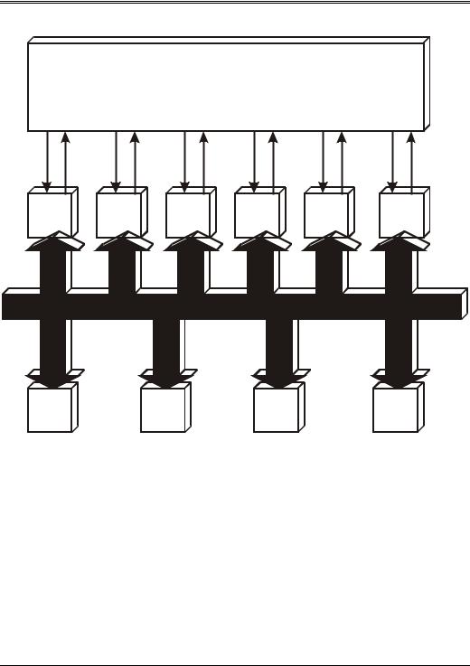
Figure 2-1 illustrates the EISA system bus structure. The basic system components are:
•System board
•ISA/EISA expansion cards
18
Chapter 2: EISA Bus Structure Overview
Central Arbitration Control
MAK1# |
MREQ1# |
MAK2# MREQ2# |
MAKn# MREQn# |
REFACK REFREQ |
CPUACK |
CPUREQ |
DMAACK |
DMAREQ |
|
|
|
|
|
|
|
|
|
Bus |
|
Bus |
|
Bus |
|
Refresh |
|
Host |
|
DMAC |
Master |
|
Master |
|
Master |
|
Logic |
|
CPU |
|
|
1 |
|
2 |
|
n |
|
|
|
|
|
|
|
|
|
|
|
|
|
|
|
|
|
EISA Bus
Slave |
|
Slave |
|
Slave |
|
System |
Card |
|
Card |
|
Card |
|
Board |
|
|
|
|
|
|
Slave |
|
|
|
|
|
|
|
Figure 2-1. The EISA Bus — a Shared Resource
The user may install two basic classes of devices on the expansion bus:
•ISA-compatible expansion cards
•EISA-compatible expansion cards
All EISA and ISA expansion devices fall into one of two categories:
•A master is a device that executes bus cycles to communicate with other devices. Any type of master can communicate with any type of slave in the system. The system board provides data bus steering logic that copies the
19

EISA System Architecture
data between data paths and translates EISA/ISA control signals when necessary.
•A slave is a device that a master reads from or writes to. A slave may be either a memory or an I/O slave.
There is only one type of ISA master — the ISA 16-bit bus master. This is a device that attaches to the ISA Bus and is capable of executing bus cycles to communicate with memory or I/O slaves. This is accomplished by interfacing the bus master card to DMA channel five, six or seven with the channel programmed to operate in cascade mode. A more detailed description of bus mastering in the ISA environment can be found in the chapter entitled “DMA and Bus Mastering” in the MindShare book entitled ISA System Architecture.
EISA System Bus Master Types
In an EISA system, there are five basic types of bus masters:
•16-bit ISA or EISA bus master — This is a 16-bit ISA or EISA device that attaches to the EISA bus and is capable of executing bus cycles to communicate with any slave. When communicating with a 32-bit EISA slave or an 8-bit ISA slave, the data bus steering logic on the system board must sometimes aid in the transfer.
•32-bit EISA bus master — This is a 32-bit device that attaches to the EISA bus and is capable of executing bus cycles to communicate with any slave. When communicating with 8 or 16-bit slaves, the data bus steering logic on the system board must sometimes aid in the transfer.
•Main CPU — The CPU may communicate with any ISA or EISA Slave or with devices resident on the CPU's local bus structure. When the microprocessor attempts to perform a transfer utilizing one or more data paths not connected to the target slave, the data bus steering logic on the system board must aid in the transfer.
•The refresh logic — Used to refresh DRAM memory throughout the system.
•DMA controllers — Used to transfer information between an I/O device and system memory.
20

Chapter 2: EISA Bus Structure Overview
Types of Slaves in EISA System
Slaves fall into the following categories:
•8-bit ISA I/O and memory slaves
•16-bit ISA I/O and memory slaves
•16-bit EISA I/O and memory slaves
•32-bit EISA I/O and memory slaves
•8, 16 or 32-bit slaves on the CPU's local bus
21

EISA System Architecture
22