

EISA System Architecture
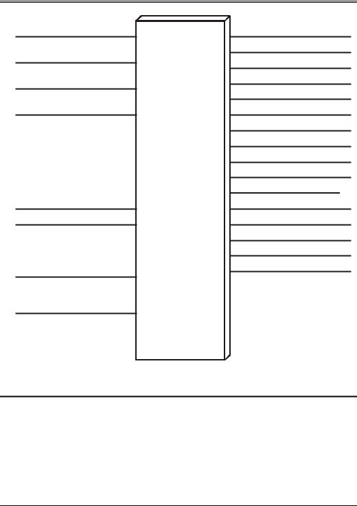
A15
A14
A13
A12
A9
A8
AEN(from DMAC)
M/IO#
EISA
System
Board
I/O
Decoder
AEN0
AEN1
AEN2
AEN3
AEN4
AEN5
AEN6
AEN7
AEN8
AEN9 AEN10 AEN11
AEN12
AEN13
AEN14
AEN15
Figure 9-2. The System Board's AEN Decoder
EISA Product Identifier
EISA expansion boards, embedded devices and system boards have a four byte product ID that can be read from I/O port addresses xC80h – xC83h, where x = 0 for the system board or the number of the expansion slot the card is installed in. For example, the system board's ID can be read from I/O addresses 0C80 – 0C83h and slot one’s ID can be read from 1C80 – 1C83h.
98

Chapter 9: EISA System Configuration
The first two bytes of the system board ID, read from I/O ports xC80 – xC81, contain a three character manufacturer's code. The three character manufacturer code is uppercase, ASCII alpha chosen by the manufacturer and registered with the firm that distributes the EISA spec. A compressed version of the ASCII code, using just the lower five bits of each character, is used. The third byte and the high-order four bits of the fourth byte are used to specify a product identifier consisting of three hex digits. The lower four bits of the fourth byte is use to specify the product revision number. Table 9-6 illustrates the format of the product ID bytes read from an expansion board. Table 9-7 illustrates the format of the product ID bytes read from an EISA system board.
To verify that an EISA expansion card is installed in a particular card slot:
•Write FFh to I/O port xC80h.
•Read one byte from xC80h.
•If the byte read equals FFh, an EISA card isn't installed in the slot. If the byte does not equal FFh and bit 7 of the byte read is zero, the card's EISA product ID can be read from xC80h – xC83h.
|
|
|
|
Table 9-6. Expansion Board Product ID Format |
|
|
Location/Bits |
|
|
Specify |
|
|
|
|
|
|
|
|
xC80, bit 7 |
|
|
not used, must be 0 |
|
|
xC80, bits 6:2 |
|
|
1st compressed ASCII character of Manufacturer's ID |
|
|
xC80, bits 1:0 |
|
|
upper two bits of 2nd compressed ASCII character of Manufac- |
|
|
|
|
|
turer's ID |
|
|
xC81, bits 7:5 |
|
|
lower three bits of 2nd compressed ASCII character of Manufac- |
|
|
|
|
|
turer's ID |
|
|
xC81, bits 4:0 |
|
|
3rd compressed ASCII character of Manufacturer's ID |
|
|
xC82, bits 7:4 |
|
|
upper hex digit of product type |
|
|
xC82, bits 3:0 |
|
|
middle hex digit of product type |
|
|
xC83, bits 7:4 |
|
|
lower hex digit of product type |
|
|
xC83, bits 3:0 |
|
|
single hex digit of product revision number |
|
99

EISA System Architecture
|
|
|
|
Table 9-7. EISA System Board Product ID Format |
|
|
Location/Bits |
|
|
Specify |
|
|
|
|
|
|
|
|
0C80, bit 7 |
|
|
not used, must be 0 |
|
|
0C80, bits 6:2 |
|
|
1st compressed ASCII character of Manufacturer's ID |
|
|
0C80, bits 1:0 |
|
|
upper two bits of 2nd compressed ASCII character of Manufac- |
|
|
|
|
|
turer's ID |
|
|
0C81, bits 7:5 |
|
|
lower three bits of 2nd compressed ASCII character of Manufac- |
|
|
|
|
|
turer's ID |
|
|
0C81, bits 4:0 |
|
|
3rd compressed ASCII character of Manufacturer's ID |
|
|
0C82, bits 7:0 |
|
|
reserved for manufacturer's use |
|
|
0C83, bits 7:3 |
|
|
reserved for manufacturer's use |
|
|
0C83, bits 2:0 |
|
|
EISA bus version |
|
EISA Configuration Registers
In an ISA machine, expansion cards are configured by setting DIP switches and/or jumpers to the desired settings. This allows the user to select options such as:
•the start address of a device ROM mounted on the card
•the start address of RAM located on the card
•the IRQ line the card utilizes
•the DMA channel the card utilizes
•the I/O address range the card responds to
Setting the switches and/or jumpers allows the user to resolve conflicts between installed expansion cards. In addition, many ISA system boards have switches and/or jumpers that are used to configure the system board options.
The EISA specification replaces the switches and/or jumpers with special I/O locations. Each of these I/O locations can contain up to eight bits that may be used to select options on the system or expansion card. Each I/O location may be thought of as a pseudo-DIP switch bank. They are configuration registers. These special I/O locations reside in the slot-specific I/O address space starting at xC80h and extending up to xCFFh, a total of 128 locations. The first four of these I/O locations are reserved for the card ID, while three of the eight bits in xC84h are reserved for special card functions. The remaining five bits in xC84h and locations xC85h – xCFFh are available for the implementation of cardspecific configuration registers.
Configuration Bits Defined by EISA Spec
100