


Chapter 7: EISA CPU and Bus Master Bus Cycles
7.If EXRDY is sampled asserted at the midpoint of Tc, the bus cycle is terminated at the end of Tc. If the current bus master has another bus cycle to perform and it uses address pipelining, the address for the next bus cycle is placed on the LA bus, the byte enable lines and M/IO#.
8.After EXRDY is sampled asserted at the midpoint of Tc, the bus cycle is terminated at the end of the BCLK cycle. The system board logic deasserts the CMD# signal. If a read bus cycle is in progress, the bus master reads the data from the data bus. If a write bus cycle is in progress, the bus master ends the bus cycle but continues to drive the data onto the data bus until the midpoint of Ts of the next bus cycle. This is done to ensure that the hold time for the currently-addressed device is satisfied.
Performance Using EISA Standard Bus Cycle
Assuming that the current bus master and the currently-addressed slave are both 32-bit devices, the BCLK frequency is 8.33MHz, and the bus master performs a series of 32-bit transfers, the transfer rate would be 16.66MB/second:
120ns per BCLK cycle x 2 BCLK cycles per transfer
=240ns per transfer, divided into one second
=4.166M transfers/second, at 4 bytes/transfer
=16.66MB/second
If the currently-addressed slave is a 16-bit device, the transfer rate would be 8.33MB/second.
Compressed Bus Cycle
General
To the authors’ knowledge, currently-available EISA chipsets do not support the EISA compressed bus cycle. For this reason, a detailed analysis of the compressed bus cycle is reserved for a future printing.
Only the main CPU can utilize EISA compressed bus cycles when communicating with EISA memory or I/O slaves that support compressed mode. Using the compressed bus cycle, the CPU can complete a transfer every 1.5 BCLK cycles. The following formula may be used to calculate the overall transfer rate when transferring a block of data between the main CPU and a slave that supports compressed bus cycles:
75

EISA System Architecture
Total Transfer = N * (1.5 BCLK periods)
where: N = the total number of bus cycles for the overall block transfer
As an example, a transfer of 64 doublewords (256 bytes) completes in 11.52 microseconds for a 32-bit transfer with a 8.33MHz BCLK, while a 16-bit transfer completes in 23.04 microseconds. This example assumes that no preempts occur during the transfer and that the addressed slave is a zero wait state device.
Using the compressed bus cycle, the CPU presents a new address every 1.5 BCLK periods (instead of two) and the system board shortens the duration of the CMD# assertion period to one-half of a BCLK period.
If a slave supports compressed bus cycles, it must assert NOWS# prior to the end of Ts. The slave must not de-assert EXRDY after asserting NOWS#. If the system board samples NOWS# asserted at the leading-edge of CMD# and the system board design supports compressed mode, the CMD# pulse width is shortened to .5 BCLK periods. Since the main CPU logic might not support compressed mode, or the current bus master might not be the main CPU, the slave must be prepared to accept CMD# with a duration of one BCLK or longer.
Performance Using Compressed Bus Cycle
If both the main CPU and the currently-addressed slave support compressed mode, the BCLK frequency is 8.33MHz, and both the master and the salve are 32-bit devices, the transfer rate for a block data transfer would be 22.22MB/second:
120ns per BCLK cycle x 1.5 BCLK cycles per transfer
=180ns per transfer, divided into one second
=5.55M transfers/second, at 4 bytes/transfer
=22.22MB/second
If the currently addressed slave is a 16-bit device, the transfer rate would be 11.11MB/second.
Burst Bus Cycle
76

Chapter 7: EISA CPU and Bus Master Bus Cycles
General
A burst transfer is used to transfer blocks of data between the current bus master and EISA memory. A burst must consist of all reads or all writes. Reads and writes may not be mixed within a burst. In other words, the state of the W/R# bus cycle definition line may not be changed during a burst. After the initial transfer in a block data transfer, each subsequent EISA Burst bus transfer can be completed in one BCLK period. The initial transfer requires the time periods consisting of Ts and Tc to transfer the first data item and for the master and slave to agree to use burst mode for the subsequent transfers. Unless wait states are inserted by the slave, each subsequent transfer can then be completed in one BCLK period. Each wait state adds one additional BCLK period. The following formula is used to calculate the total transfer time:
Total Transfer Time = (1 + Twi + N) * one BCLK period
where: Twi = wait states inserted per transfer
N = number of bus cycles for overall transfer
As an example, a transfer of 64 doublewords (256 bytes) completes in 7.8 microseconds for a 32-bit transfer with a 8.33MHz BCLK, while a 16-bit transfer completes in 15.6 microseconds. This example assumes that no preempts occur during the transfer and the addressed slave is a zero wait state device.
Analysis of EISA Burst Transfer
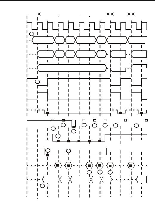
The timing diagram in figure 7-2 illustrates the timing for five transfers performed using burst mode. The following numbered steps correspond to the reference points in the illustration.
A 16-bit burst transfer is identical with the exception that EX16# is generated by the slave instead of EX32#.
1.The current bus master can use address pipelining to output the first address and M/IO# early.
2.At the beginning of the first bus cycle in the transfer, the current EISA bus master activates the START# signal. Assertion of START# indicates that the bus master has placed a valid address and bus cycle definition on the bus. The EISA bus controller (EBC) on the system board samples START# asserted and recognizes that an EISA bus master, rather than an ISA bus master, has initiated a bus cycle. In response, the EBC generates BALE during
77

EISA System Architecture
Ts. This is done in case the EISA bus master is addressing an ISA device. In addition, the bus master sets the byte enable lines and W/R# to the appropriate state. W/R# remains in the selected state (write or read) throughout the burst transfer.
3.If this is a write transfer, the bus master starts to drive the data onto the data bus at the midpoint of Ts.
4.At the end of Ts, the current bus master and the system board logic sample EX16# and EX32#. The assertion of either of these signals indicates that the currently-addressed device is an EISA device and what data paths it is capable of using. The bus master deasserts START# and the system board logic asserts CMD# to indicate that the data phase has begun. If the bus master is capable of using burst transfers, it samples SLBURST# to determine if the addressed slave also supports burst. In this example, SLBURST# is sampled asserted, indicating that the slave supports burst mode.
5.In response to sampling SLBURST# asserted, the bus master asserts MSBURST# at the midpoint of Tc to indicate to the slave that it also supports burst mode and will use it for the remaining transfers in the burst. Also, the bus master samples EXRDY at the midpoint of Tc to determine if the addressed slave will be ready to complete the first transfer at the end of the current Tc. In this example, EXRDY is sampled asserted, indicating that the first transfer can be completed at the end of this Tc period. In response. the bus master pipelines out the second address starting at the midpoint of Tc.
6.At the end of the first Tc period, the bus master completes the first transfer in the burst. If a read burst is in progress, the bus master reads the data from the appropriate data paths. If a write burst is in progress, the bus master starts to drive the data for the second transfer onto the appropriate data paths. The slave samples MSBURST# at the end of each Tc period to determine if the bus master will use burst mode for the remaining transfers. In this example, MSBURST# is sample asserted, so the burst transfer continues.
7.At the midpoint of the second Tc, the bus master samples EXRDY to determine if the slave will be ready to complete the second transfer at the end of this Tc period. In this example, it is sampled asserted, indicating that the slave will be ready. In response, the bus master begins to drive the third address out at the midpoint of Tc.
8.At the end of the second Tc, the slave samples MSBURST# again to determine if the bus master is still bursting. The asserted state indicates that it is. The bus master completes the second transfer. If a read burst is in progress, the bus master reads the data from the appropriate data paths. If a write burst is in progress, the bus master starts to drive the data for the third transfer onto the appropriate data paths.
78

Chapter 7: EISA CPU and Bus Master Bus Cycles
9.At the midpoint of the third Tc, the bus master samples EXRDY to determine if the slave will be ready to complete the third transfer at the end of this Tc period. In this example, EXRDY is sampled deasserted, indicating it will not be ready. This causes the bus master to insert a wait state of one Tc duration to stretch the data transfer time for the third transfer. If a read transfer is in progress, the bus master doesn’t read the third transfer's data from the bus at the end of this Tc. If a write transfer, the bus master continues to drive the data for the third transfer onto the data bus during the next Tc. The bus master pipelines out the address for the fourth transfer, however, starting at the midpoint of the third Tc period.
10.At the midpoint of the fourth Tc, the bus master samples EXRDY to determine if the slave will be ready to complete the third transfer at the end of this Tc period. Since EXRDY is sampled asserted, it will be ready. The bus master does not pipeline out the address for the fifth transfer yet and continues to drive the data for the third transfer onto the data bus.
11.The bus master completes the third transfer. If a read burst is in progress, the bus master reads the data from the appropriate data paths. If a write burst is in progress, the bus master starts to drive the data for the fourth transfer onto the appropriate data paths.
12.At the midpoint of the fifth Tc period, the bus master samples EXRDY# to determine if the slave will be ready to end the fourth transfer at the end of the current Tc period. Since EXRDY is sampled asserted, the slave will be ready to end the transfer. The bus master also pipelines out the fifth address at the midpoint of Tc.
13.The bus master completes the fourth transfer. If a read burst is in progress, the bus master reads the data from the appropriate data paths. If a write burst is in progress, the bus master starts to drive the data for the fifth transfer onto the appropriate data paths.
14.At the midpoint of the sixth Tc, the bus master samples EXRDY# to determine if the slave will be ready to end the fifth transfer at the end of the current Tc period. Since EXRDY is sampled asserted, the slave will be ready to end the transfer. Since this is the end of the sample burst, the bus master de-activates MSBURST# to inform the slave that the last transfer of the burst is in progress. In this example, the bus master pipelines out the next address at the midpoint of Tc. In this example, the bus master is addressing a device other than the memory slave, causing the slave to release SLBURST#.
15.At the end of the sixth Tc period, the bus master completes the last transfer of the burst. If a read burst is in progress, the bus master reads the data from the appropriate data paths. If a write burst is in progress, the bus master ends the transfer and ceases to drive the data bus. This completes the example burst transfer.
79

EISA System Architecture
16.The bus cycle following the burst is a standard EISA bus cycle. Since the bus master is setting W/R# low, it is a read. The bus master samples EXRDY asserted at the midpoint of Tc and reads the data from the data bus at the end of Tc and ends the bus cycle.
17.The next bus cycle is also a standard EISA bus cycle. The high on W/R# indicates that a write is in progress. The bus master begins to drive the data onto the data bus at the midpoint of Ts, samples EXRDY asserted at the midpoint of Tc, and ends the bus cycle at the end of Tc.
80
Chapter 7: EISA CPU and Bus Master Bus Cycles
|
|
|
|
|
|
|
|
|
|
|
|
|
|
|
|
|
|
|
Bus |
|
|
Bus |
|
|
|||||
|
|
|
|
|
Burst Transfer |
|
|
|
|
|
|
Cycle |
|
|
|
Cycle |
|
||||||||||||
Ts |
|
Tc |
|
Tc |
|
|
Tc |
|
Tc |
|
|
Tc |
|
Tc |
|
|
Ts |
|
|
Tc |
|
|
Ts |
|
|
Tc |
|||
|
|
|
|
|
|
|
|
|
|
|
|
|
|||||||||||||||||
|
|
|
|
|
|
||||||||||||||||||||||||
|
|
|
|
|
|||||||||||||||||||||||||
|
|
|
|
|
|
|
|
|
|
|
|
|
|
|
|
|
|
|
|
|
|
|
|
|
|
|
|
|
|
BCLK 
1
LA2:LA31
M/IO#
BE0#:BE3#
W/R#
2
START#
CMD#
EX16#
EX32#
|
|
|
|
|
|
|
|
|
|
|
|
|
|
|
|
|
|
|
|
|
|
|
|
|
|
|
|
|
|
|
|
|
|
|
|
|
|
EXRDY |
|
|
|
|
7 |
|
|
10 |
12 |
|
|
14 |
|
16 |
|
|
|
|
17 |
|
|
|
|||||||||||||||
5
9
6
MSBURST#
|
|
|
|
|
|
|
|
|
|
|
|
|
|
|
|
|
|
|
|
|
|
|
|
|
|
|
|
|
|
|
|
|
|
|
|
|
|
|
|
|
|
|
|
|
|
|
|
4 |
8 |
|
|
|
|
|
|
|
|
||
SLBURST#
Read
Data
11 13 15
Write
Data
3
Figure 7-2. The EISA Burst Transfer
81