Table 7.2 Variable length decoding example: MPEG-4 Visual TCOEF
State |
Input |
Next state |
VLC |
Output (last, run, level) |
|
|
|
|
|
0 |
0 |
1 |
0.. |
– |
|
1 |
2 |
1.. |
– |
1 |
0 |
..later state |
00.. |
|
|
1 |
..later state |
01.. |
|
2 |
0 |
0 |
10s |
(0,0,s1) |
|
1 |
3 |
11.. |
|
3 |
0 |
0 |
110s |
(0,1,s1) |
|
1 |
4 |
111.. |
– |
4 |
0 |
0 |
1110s |
(0,2,s1) |
|
1 |
0 |
1111s |
(0,0,s2) |
etc. |
. . . |
. . . |
. . . |
. . . |
|
|
|
|
|
decoded syntax element (or error indication) is returned and the decoder restarts from the initial state. Table 7.2 shows the first part of the decoding sequence for the MPEG-4 Visual TCOEF (transform coefficient) context, starting with state 0. If the input bit is 0, the next state is state 1 and if the input is 1, the next state is 2. From state 2, if the input is 0, the decoder has ‘found’ a valid VLC, 10. In this context it is necessary to decode 1 more bit at the end of each VLC (the sign bit, s, indicating whether the level is positive or negative), after which it outputs the relevant syntax element (0, 1 or +/−1 in this case) and returns to state 0. Note that when a syntax element containing ‘last = 1’ is decoded, we have reached the end of the block of coefficients and it is necessary to reset or change the context.
In this example, the decoder can process one input bit at each stage (e.g. one bit per clock cycle in a hardware implementation). This may be too slow for some applications in which case a more sophisticated architecture that can examine multiple bits (or entire VLCs) in one operation may be required. Examples of architectures for variable-length coding and decoding include [26–29].
7.2.6.3 Arithmetic Coding
An arithmetic encoder (see Chapter 3) encodes each syntax element through successive refinement of a fractional number. Arithmetic coding has the potential for greater compression efficiency than any variable-length coding algorithm (due to its ability to represent fractional probability distributions accurately). In practice, it is usually necessary to represent the fractional numbers produced by an arithmetic encoder using fixed-point values within a limited dynamic range. Some implementation issues for the context-based arithmetic coder adopted for H.264 Main Profile are discussed in Chapter 6 and a detailed overview of the CABAC scheme is given in [30].
7.3 INPUT AND OUTPUT
7.3.1 Interfacing
Figure 7.17 shows a system in which video frames are encoded, transmitted or stored and decoded. At the input to the encoder (A) and the output of the decoder (D), data are in the
242 |
|
|
|
|
|
|
|
|
|
|
DESIGN AND PERFORMANCE |
|
• A |
|
B |
|
|
|
|
|
|
C |
|
D |
|
|
|
|
|
|
|
|
|
|
|
|
|
|
|
|
|
|
|
video |
|
|
encode |
|
|
network |
|
network or |
|
|
network |
|
|
decode |
|
video |
|
frames |
|
|
adaptation |
|
storage |
adaptation |
|
|
|
frames |
|
|
|
|
|
|
|
|
|
|
|
|
|
|
|
|
|
|
|
|
|
|
|
|
|
|
|
Figure 7.17 Video CODEC interfaces
format of uncompressed video frames, each represented by a set of samples, typically in the YCbCr colour space using one of the sampling structures described in Chapter 2 (4:4:4, 4:2:2 or 4:2:0). There are a number of different methods of combining the three components of each frame, including interleaved (samples of Y, Cb and Cr are interleaved together in raster scan order), concatenated (the complete Y component for a frame is followed by the Cb and then Cr components) and using separate buffers or memory areas to store each of the three components. The choice of method may depend on the application. For example, using separate buffers for the Y, Cb and Cr components may be suitable for a software CODEC; a hardware CODEC with limited memory and/or a requirement for low delay may use an interleaved format.
At the output of the encoder (B) and the input to the decoder (C) the data consist of a sequence of bits representing the video sequence in coded form. The H.264 and MPEG-4 Visual standards use fixed length codes, variable-length codes and/or arithmetic coding to represent the syntax elements of the compressed sequence. The coded bitstream consists of continuous sequences of bits, interspersed with fixed-length ‘marker’ codes. Methods of mapping this bitstream to a transport or storage mechanism (‘delivery mechanism’) include the following.
Bit-oriented: If the delivery mechanism is capable of dealing with an arbitrary number of bits, the bitstream may be transmitted directly (optionally multiplexed with associated data such as coded audio and ‘side’ information).
Byte-oriented: Many delivery mechanisms (e.g. file storage or network packets) require data to be mapped to an integral number of bytes or words. It may be necessary to pad the coded data at the end of a unit (e.g. slice, picture, VOP or sequence) to make an integral number of bytes or words.
Packet-oriented: Both MPEG-4 Visual and H.264 support the concept of placing a complete coded unit in a network packet. A video packet or NAL unit packet contains coded data that corresponds to a discrete coded unit such as a slice (a complete frame or VOP or a portion of a frame or VOP) (see Section 6.7).
7.3.2 Pre-processing
The compression efficiency of a video CODEC can be significantly improved by preprocessing video frames prior to encoding. Problems with the source material and/or video capture system may degrade the coding performance of a video encoder. Camera noise (introduced by the camera and/or the digitisation process) is illustrated in Figure 7.18. The top
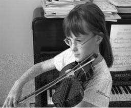
Figure 7.18 Image showing camera noise (lower half)
half of this image is relatively noise-free and this is typical of the type of image captured by a high-quality digital camera. Images captured from low-quality sources are more likely to contain noise (shown in the lower half of this figure). Camera noise may appear in higher spatial frequencies and change from frame to frame. An encoder will ‘see’ this noise as a high-frequency component that is present in the motion-compensated residual and is encoded together with the desired residual data, causing an increase in the coded bitrate. Camera noise can therefore significantly reduce the compression efficiency of an encoder. By filtering the input video sequence prior to encoding it may be possible to reduce camera noise (and hence improve compression efficiency). The filter parameters should be chosen with care, to avoid filtering out useful features of the video sequence.
Another phenomenon that can reduce compression efficiency is camera shake, small movements of the camera between successive frames, characteristic of a hand-held or poorly stabilised camera. These are ‘seen’ by the encoder as global motion between frames. Motion compensation may partly correct the motion but block-based motion estimation algorithms are not usually capable of correcting fully for camera shake and the result is an increase in residual energy and a drop in compression performance. Many consumer and professional camcorders incorporate image stabilisation systems that attempt to compensate automatically for small camera movements using mechanical and/or image processing methods. As well as improving the appearance of the captured video sequence, this has the effect of improving compression performance if the material is coded using motion compensation.
7.3.3 Post-processing
Video compression algorithms that incorporate quantisation (such as the core algorithms of MPEG-4 Visual and H.264) are inherently lossy, i.e. the decoded video frames are not identical to the original. The goal of any practical CODEC is to minimise distortion and maximise compression efficiency. It is often possible to reduce the actual or apparent distortion in the decoded video sequence by processing (filtering) the decoded frames. If the filtered decoded frames are then used for compensation, the filtering process can have the added benefit of improving motion-compensated prediction and hence compression efficiency.
• |
DESIGN AND PERFORMANCE |
244 |
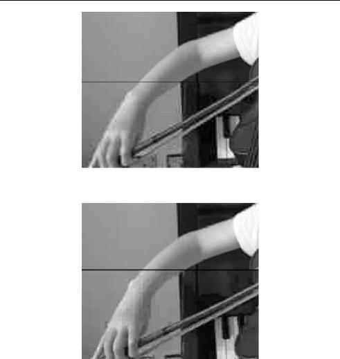
Figure 7.19 Distortion introduced by MPEG-4 Visual encoding (lower half)
Figure 7.20 Distortion introduced by H.264 encoding (lower half)
Block transform-based CODECs introduce characteristic types of distortion into the decoded video data. The lower half of Figure 7.19 shows typical distortion in a frame encoded and decoded using MPEG-4 Simple Profile (the upper half is the original, uncompressed frame). This example shows ‘blocking’ distortion (caused by mismatches at the boundaries of reconstructed 8 × 8 blocks) and ‘ringing’ distortion (faint patterns along the edges of objects, caused by the ‘break through’ of DCT basis patterns). Blocking is probably the most visually obvious (and therefore the most important) type of distortion introduced by video compression. Figure 7.20 (lower half) shows the result of encoding and decoding using H.264 without loop filtering. The smaller transform size in H.264 (4 × 4 rather than 8 × 8 samples) means that the blocking artefacts are correspondingly smaller, but are still obvious1.
1 The compressed halves of each of these figures were encoded at different bitrates.

|
|
|
|
|
|
ENCODER |
|
|
|
|
|
|
|
DECODER |
|
|
|
|
|
|
|
|
|
|
|
|
|
|
|
|
|
|
|
|
|
|
|
|
|
|
|
|
|
|
|
|
|
|
|
|
|
|
|
|
|
|
|
|
|
|
|
|
|
|
|
|
|
|
|
|
|
|
|
|
|
motion- |
|
|
|
transform, |
|
decoding, |
|
|
|
motion- |
|
|
|
|
|
|
|
|
|
|
|
|
|
|
|
|
input |
|
|
|
|
compensated |
|
|
|
quantise, |
|
|
|
|
rescaling, |
|
|
|
compensated |
|
|
|
|
|
|
decoded |
|
|
filter |
|
|
|
|
|
|
|
|
|
|
|
|
|
inverse |
|
|
|
|
|
|
|
|
|
|
|
|
|
frame |
prediction |
|
|
|
etc. |
|
|
|
|
|
|
|
reconstruction |
|
|
|
|
|
|
frame |
|
|
|
|
|
|
|
|
|
|
|
|
transform |
|
|
|
|
|
|
|
|
|
|
|
|
|
|
|
|
|
|
|
|
|
|
|
|
|
|
|
|
|
|
|
|
|
|
|
|
|
|
|
|
|
|
|
|
|
|
|
|
|
|
|
|
|
|
|
|
|
|
|
|
|
|
|
|
|
|
|
|
|
|
|
|
|
|
|
|
|
|
|
|
|
|
|
|
|
|
|
|
|
|
|
|
|
|
|
|
|
|
|
|
|
|
|
|
|
|
|
|
|
|
|
|
|
|
|
|
|
|
|
|
|
|
|
|
|
|
|
|
|
|
|
|
|
|
|
|
|
|
reconstructed |
|
|
|
|
|
|
|
|
|
|
|
|
|
reconstructed |
|
|
|
|
|
|
|
|
|
|
|
|
|
|
|
|
|
|
|
|
|
|
|
|
|
|
|
|
|
|
|
|
|
|
|
|
|
|
|
|
|
|
|
|
|
|
|
|
|
|
|
|
|
|
frame |
|
|
|
|
|
|
|
|
|
|
|
|
frame |
|
|
|
|
|
|
|
|
|
|
|
|
|
|
|
|
|
|
|
|
|
|
|
|
|
|
Figure 7.21 Post-filter implementation |
|
|
|
|
|
|
|
|
|
|
|
|
|
|
|
|
|
|
|
|
|
|
ENCODER |
|
|
|
|
DECODER |
|
|
|
|
|
|
|
|
|
|
|
|
|
|
|
|
|
|
|
|
|
|
|
|
|
|
|
|
|
|
|
|
|
|
|
|
|
|
|
|
|
|
|
|
|
|
|
|
|
|
|
|
|
|
|
|
|
|
|
|
|
|
|
|
|
|
|
|
|
|
|
|
|
|
|
|
|
|
|
|
|
|
|
|
|
|
|
|
|
|
|
|
|
|
|
motion- |
|
|
|
transform, |
|
|
|
|
decoding, |
|
|
|
motion- |
|
|
|
|
|
|
|
|
|
|
|
|
|
|
|
|
input |
|
|
compensated |
|
|
|
quantize, |
|
|
|
|
rescaling, |
|
|
|
compensated |
|
|
|
|
|
|
filter |
|
|
|
decoded |
|
|
frame |
prediction |
|
|
|
etc. |
|
|
|
|
inverse |
|
|
|
reconstruction |
|
|
|
|
|
|
|
|
|
|
|
|
frame |
|
|
|
|
|
|
|
|
|
|
|
|
|
|
|
|
|
|
|
|
transform |
|
|
|
|
|
|
|
|
|
|
|
|
|
|
|
|
|
|
|
|
|
|
|
|
|
|
|
|
|
|
|
|
|
|
|
|
|
|
|
|
|
|
|
|
|
|
|
|
|
|
|
|
|
|
|
|
|
|
|
|
|
|
|
|
|
|
|
|
|
|
|
|
|
|
|
|
|
|
|
|
|
|
|
|
|
|
|
|
|
|
|
|
|
|
|
|
|
|
|
|
|
|
|
|
|
|
reconstructed |
|
filter |
|
|
|
|
|
|
|
|
|
|
|
reconstructed |
|
|
|
|
|
|
|
|
|
|
|
|
|
|
|
|
|
|
|
|
|
frame |
|
|
|
|
|
|
|
|
|
|
|
frame |
|
|
|
|
|
|
|
|
|
|
|
|
|
|
|
|
|
|
|
|
|
|
|
|
|
|
|
|
|
|
|
|
|
|
|
|
|
|
|
|
|
|
|
|
|
|
|
|
|
|
|
|
|
|
|
|
|
|
|
|
|
|
|
|
|
|
|
|
|
|
|
|
|
|
|
|
|
|
|
|
|
|
|
|
|
|
|
|
|
Figure 7.22 Loop filter implementation
Filters to reduce blocking (de-blocking) and/or ringing effects (de-ringing) are widely used in practical CODECs. Many filter designs have been proposed and implemented, ranging from relatively simple algorithms to iterative algorithms that are many times more complex than the encoding and decoding algorithms themselves [31–34]. The goal of a de-blocking or de-ringing filter is to minimise the effect of blocking or ringing distortion whilst preserving important features of the image. MPEG-4 Visual describes a deblocking filter and a deringing filter: these are ‘informative’ parts of the standard and are therefore optional. Both filters are designed to be placed at the output of the decoder (Figure 7.21). With this type of post-filter, unfiltered decoded frames are used as the reference for motion-compensated reconstruction of further frames. This means that the filters improve visual quality at the decoder but have no effect on the encoding and decoding processes.
It may be advantageous to place the filter inside the encoding and decoding ‘loops’ (Figure 7.22). At the decoder, the filtered decoded frame is stored for further motioncompensated reconstruction. In order to ensure that the encoder uses an identical reference frame, the same filter is applied to reconstructed frames in the encoder and the encoder uses the filtered frame as a reference for further motion estimation and compensation. If the quality of the filtered frame is better than that of an unfiltered decoded frame, then it will provide a better match for further encoded frames, resulting in a smaller residual after motion compensation and hence improved compression efficiency. H.264 makes use of this type of loop filter (see Chapter 6 for details of the filter algorithm). One disadvantage of incorporating the filter into the loop is that it must be specified in the standard (so that any decoder can successfully repeat the filtering process) and there is therefore limited scope for innovative filter designs.