


• |
VIDEO CODING CONCEPTS |
34 |
|
frame |
|
|
reference |
|
|
area |
|
|
search |
|
|
best |
match |
|
|
|
|
|
|
|
|
|
e fram current
macroblock current
Figure 3.9 Motion estimation
and transmitted together with a motion vector describing the position of the best matching region (relative to the current macroblock position). Within the encoder, the residual is encoded and decoded and added to the matching region to form a reconstructed macroblock which is stored as a reference for further motion-compensated prediction. It is necessary to use a decoded residual to reconstruct the macroblock in order to ensure that encoder and decoder use an identical reference frame for motion compensation.
There are many variations on the basic motion estimation and compensation process. The reference frame may be a previous frame (in temporal order), a future frame or a combination of predictions from two or more previously encoded frames. If a future frame is chosen as the reference, it is necessary to encode this frame before the current frame (i.e. frames must be encoded out of order). Where there is a significant change between the reference and current frames (for example, a scene change), it may be more efficient to encode the macroblock without motion compensation and so an encoder may choose intra mode (encoding without motion compensation) or inter mode (encoding with motion compensated prediction) for each macroblock. Moving objects in a video scene rarely follow ‘neat’ 16 × 16-pixel boundaries and so it may be more efficient to use a variable block size for motion estimation and compensation. Objects may move by a fractional number of pixels between frames (e.g. 2.78 pixels rather than 2.0 pixels in the horizontal direction) and a better prediction may be formed by interpolating the reference frame to sub-pixel positions before searching these positions for the best match.
3.3.5 Motion Compensation Block Size
Two successive frames of a video sequence are shown in Figure 3.10 and Figure 3.11. Frame 1 is subtracted from frame 2 without motion compensation to produce a residual frame
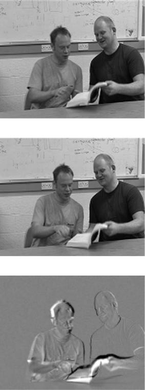
Figure 3.10 Frame 1
Figure 3.11 Frame 2
Figure 3.12 Residual (no motion compensation)
• |
VIDEO CODING CONCEPTS |
36 |
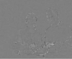
Figure 3.13 Residual (16 × 16 block size)
Figure 3.14 Residual (8 × 8 block size)
(Figure 3. 12). The energy in the residual is reduced by motion compensating each 16 × 16 macroblock (Figure 3.13). Motion compensating each 8 × 8 block (instead of each 16 × 16 macroblock) reduces the residual energy further (Figure 3.14) and motion compensating each 4 × 4 block gives the smallest residual energy of all (Figure 3.15). These examples show that smaller motion compensation block sizes can produce better motion compensation results. However, a smaller block size leads to increased complexity (more search operations must be carried out) and an increase in the number of motion vectors that need to be transmitted. Sending each motion vector requires bits to be sent and the extra overhead for vectors may outweigh the benefit of reduced residual energy. An effective compromise is to adapt the block size to the picture characteristics, for example choosing a large block size in flat, homogeneous regions of a frame and choosing a small block size around areas of high detail and complex
TEMPORAL MODEL |
• |
|
37 |
|
|
Figure 3.15 Residual (4 × 4 block size)
motion. H.264 uses an adaptive motion compensation block size (Tree Structured motion compensation, described in Chapter 6.
3.3.6 Sub-pixel Motion Compensation
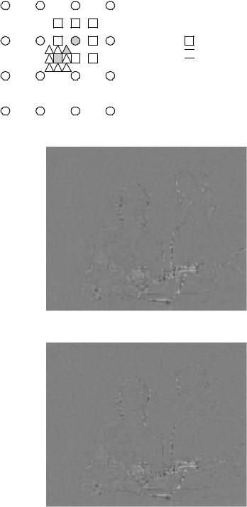
Figure 3.16 shows a close-up view of part of a reference frame. In some cases a better motion compensated prediction may be formed by predicting from interpolated sample positions in the reference frame. In Figure 3.17, the reference region luma samples are interpolated to halfsamples positions and it may be possible to find a better match for the current macroblock by searching the interpolated samples. ‘Sub-pixel’ motion estimation and compensation1 involves searching sub-sample interpolated positions as well as integer-sample positions, choosing the position that gives the best match (i.e. minimises the residual energy) and using the integeror sub-sample values at this position for motion compensated prediction. Figure 3.18 shows the concept of a ‘quarter-pixel’ motion estimation. In the first stage, motion estimation finds the best match on the integer sample grid (circles). The encoder searches the half-sample positions immediately next to this best match (squares) to see whether the match can be improved and if required, the quarter-sample positions next to the best half-sample position (triangles) are then searched. The final match (at an integer, halfor quarter-sample position) is subtracted from the current block or macroblock.
The residual in Figure 3.19 is produced using a block size of 4 × 4 samples using halfsample interpolation and has lower residual energy than Figure 3.15. This approach may be extended further by interpolation onto a quarter-sample grid to give a still smaller residual (Figure 3.20). In general, ‘finer’ interpolation provides better motion compensation performance (a smaller residual) at the expense of increased complexity. The performance gain tends to diminish as the interpolation steps increase. Half-sample interpolation gives a significant gain over integer-sample motion compensation, quarter-sample interpolation gives a moderate further improvement, eighth-sample interpolation gives a small further improvement again and so on.
1 The terms ‘sub-pixel’, ‘half-pixel’ and ‘quarter-pixel’ are widely used in this context although in fact the process is usually applied to luma and chroma samples, not pixels.

• |
VIDEO CODING CONCEPTS |
38 |
2 |
|
|
|
|
|
|
|
4 |
|
|
|
|
|
|
|
6 |
|
|
|
|
|
|
|
8 |
|
|
|
|
|
|
|
10 |
|
|
|
|
|
|
|
12 |
|
|
|
|
|
|
|
14 |
|
|
|
|
|
|
|
16 |
4 |
6 |
8 |
10 |
12 |
14 |
16 |
2 |
Figure 3.16 Close-up of reference region
5 |
|
|
|
|
|
10 |
|
|
|
|
|
15 |
|
|
|
|
|
20 |
|
|
|
|
|
25 |
|
|
|
|
|
30 |
|
|
|
|
|
5 |
10 |
15 |
20 |
25 |
30 |
Figure 3.17 Reference region interpolated to half-pixel positions
TEMPORAL MODEL |
• |
|
39 |
|
|
Key :
 Integer search positions
 Best integer match
Half-pel search positions

 Best half-pel match
 Quarter-pel search positions
 Best quarter-pel match
Figure 3.18 Integer, half-pixel and quarter-pixel motion estimation
Figure 3.19 Residual (4 × 4 blocks, half-pixel compensation)
Figure 3.20 Residual (4 × 4 blocks, quarter-pixel compensation)
40 |
|
|
|
VIDEO CODING CONCEPTS |
||||||||
|
|
|
|
|
|
|
|
|
||||
• |
Table 3.1 SAE of residual frame after motion compensation (16 × 16 block size) |
|
||||||||||
Sequence |
No motion compensation |
Integer-pel Half-pel Quarter-pel |
||||||||||
|
|
‘Violin’, QCIF |
171945 |
153475 |
128320 |
113744 |
|
|
||||
|
|
‘Grasses’, QCIF |
248316 |
245784 |
228952 |
215585 |
|
|
||||
|
|
‘Carphone’, QCIF |
102418 |
73952 |
56492 |
47780 |
|
|
||||
|
|
|
|
|
|
|
|
|
|
|
|
|
|
|
|
|
|
|
|
|
|
|
|
|
|
|
|
|
|
|
|
|
|
|
|
|
|
|
|
|
|
|
|
|
|
|
|
|
|
|
|
|
|
|
|
|
|
|
|
|
|
|
|
|
|
|
|
|
|
|
|
|
|
|
|
|
|
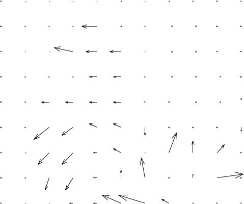
Figure 3.21 Motion vector map (16 × 16 blocks, integer vectors)
Some examples of the performance achieved by sub-pixel motion estimation and compensation are given in Table 3.1. A motion-compensated reference frame (the previous frame in the sequence) is subtracted from the current frame and the energy of the residual (approximated by the Sum of Absolute Errors, SAE) is listed in the table. A lower SAE indicates better motion compensation performance. In each case, sub-pixel motion compensation gives improved performance compared with integer-sample compensation. The improvement from integer to half-sample is more significant than the further improvement from halfto quartersample. The sequence ‘Grasses’ has highly complex motion and is particularly difficult to motion-compensate, hence the large SAE; ‘Violin’ and ‘Carphone’ are less complex and motion compensation produces smaller SAE values.
TEMPORAL MODEL |
• |
||||||
41 |
|
||||||
|
|
|
|
|
|
|
|
|
|
|
|
|
|
|
|
|
|
|
|
|
|
|
|
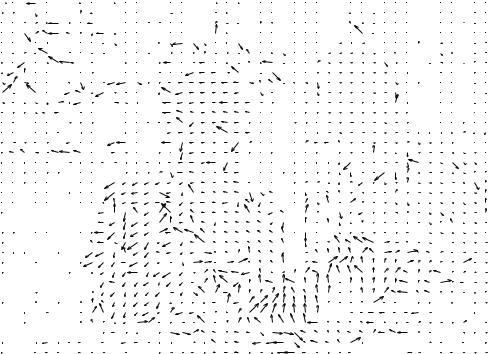
Figure 3.22 Motion vector map (4 × 4 blocks, quarter-pixel vectors)
Searching for matching 4 × 4 blocks with quarter-sample interpolation is considerably more complex than searching for 16 × 16 blocks with no interpolation. In addition to the extra complexity, there is a coding penalty since the vector for every block must be encoded and transmitted to the receiver in order to reconstruct the image correctly. As the block size is reduced, the number of vectors that have to be transmitted increases. More bits are required to represent halfor quarter-sample vectors because the fractional part of the vector (e.g. 0.25, 0.5) must be encoded as well as the integer part. Figure 3.21 plots the integer motion vectors that are required to be transmitted along with the residual of Figure 3.13. The motion vectors required for the residual of Figure 3.20 (4 × 4 block size) are plotted in Figure 3.22, in which there are 16 times as many vectors, each represented by two fractional numbers DX and DY with quarterpixel accuracy. There is therefore a tradeoff in compression efficiency associated with more complex motion compensation schemes, since more accurate motion compensation requires more bits to encode the vector field but fewer bits to encode the residual whereas less accurate motion compensation requires fewer bits for the vector field but more bits for the residual.
3.3.7 Region-based Motion Compensation
Moving objects in a ‘natural’ video scene are rarely aligned neatly along block boundaries but are likely to be irregular shaped, to be located at arbitrary positions and (in some cases) to change shape between frames. This problem is illustrated by Figure 3.23, in which the