

Broadband Packet Switching Technologies
.pdfATM ADAPTATION LAYER |
431 |
Fig. A.27 Generic AAL protocol sublayer model.
As shown in Figure A.27, the AAL is subdivided into two sublayers: the segmentation and reassembly ŽSAR. sublayer and the convergence sublayer ŽCS.. The SAR sublayer performs the segmentation of user information into the ATM cell payloads. The CS maps the specific user requirements onto the ATM transport network. The functions performed at the CS differ for each of the services, whereas the SAR sublayer provides the same functions to all the services.
The CS is further divided into two parts: the common part convergence sublayer ŽCPCS., which is common to all users of AAL services, and the service-specific convergence sublayer ŽSSCS., which depends on the characteristics of the user’s traffic. Figure A.27 shows how these sublayers SAR, CPCS, and SSCS are related to each other. The SSCS can be null, meaning that it need not be implemented, whereas the CPCS is always present. It is apparent that the protocol functionality performed at the SAR and CPCS is common to all AAL users.
A.5.1 AAL Type 1
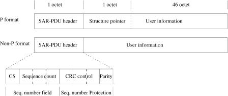
AAL1 is used for CBR services that require tight delay and jitter control between the two end systems, for example, emulated n 64 kbitrs channels or T1 or E1 facilities. As shown in Figure A.28, the 47-byte SAR-PDU
432 SONET AND ATM PROTOCOLS
Fig. A.28 AAL1 SAR PDU format.
payload used by CS has two formats, called P and non-P. In the non-P format, the entire SAR PDU is filled with user information.
The P-format is used in the structured data transfer mode, where a structured data set, a byte stream, is transferred between source and destination. The structured data set is pointed at by a pointer that is placed at the first byte of the 47-byte payload, and thus only 46 bytes are used to carry the user’s information. The pointer is carried by even-numbered Ž0, 2, 4, 6. SAR PDUs, where the convergence sublayer indicator ŽCSI. is set to 1. Since the pointer is transferred in every two PDUs, it needs to point to any byte in the structured data set, that is, up to 93 bytes Ž46 q 47.. Thus, 7 bits are used in the one-byte pointer to address the first byte of an n 64 kbitrs structure.
The first byte of the SAR PDU consists of a 1-bit CSI, a 3-bit sequence count, a 3-bit cyclic redundancy check ŽCRC., and a parity bit. The CSI bit carries the CS indication. The sequence count carries the sequence number of the SAR PDUs Ž0 to 7.. The CSI bit and the sequence count are protected by a 3-bit CRC. The resulting 7-bit field is protected by an even-parity check bit. The CSI and the sequence count values are provided by the CS sublayer. Such a 4-bit sequence number protection field is able to correct single-bit errors and to detect multiple-bit errors. By using the sequence count, the receiver will be able to detect any cell loss if the number of lost cells is not an integer multiple of 16.
The AAL1 convergence sublayer provides two methods to support asynchronous CBR services where the clocks are not locked to a network clock. The two methods are adapti®e clock and synchronous residual time stamp
ŽSRTS.. With the SRTS technique, an accurate reference network is supposed to be available at both transmitter and receiver. The timing information about the difference between the source clock and the network rate is conveyed by the CSI bit. The difference is bounded to 4-bit precision, and thus the source clock’s stability tolerance is 2 parts per million Žppm.. The 4
ATM ADAPTATION LAYER |
433 |
bits of timing information are carried in the CSI field of four SAR PDUs with an odd sequence count Ž1, 3, 5, 7.. The receiver can thus regenerate the source clock rate with required accuracy by using the CSI field.
A.5.2 AAL Type 2
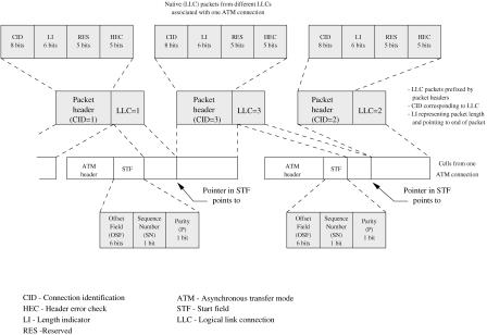
AAL2 is recently standardized and is designed for low-bit-rate, delay-sensi- tive applications that generate short, variable-length packets. A motivating application for AAL2 was low-bit-rate voice, where the delay to fill the payload of an ATM cell with the encoded speech from a single voice source would have degraded performance because of its large assembly delay. Thus, a key attribute of AAL2 is the ability to multiplex higher-layer packets from different native connections, called logical link connections ŽLLCs. Žup to 255., onto a single ATM virtual channel connection ŽVCC. without regard to the cell boundaries. In other words, AAL2 does not require that each encapsulated packet fit within a single ATM payload, but rather allows packets to span across payloads. A connection identification ŽCID. field is used in the packet header to identify the LLC to which a packet belongs. A length indicator ŽLI. field is used to identify the boundaries of variable-length LLC packets.
Figure A.29 shows the AAL2 SAR-PDU format, where the start field ŽSTF. is located at the beginning of each ATM cell and the packet header
Fig. A.29 AAL2 SAR PDU format.
434 SONET AND ATM PROTOCOLS
precedes each native packet. The packet header is 3 bytes long. The CID field is 8 bits long and identifies the LLC for the packet. The LI field comprises 6 bits and indicates the length of the LLC packet. When the LI points beyond the end of the current ATM cell, the packet is split between cells. The HEC field comprises 5 bits and provides error detection over the packet header. Five bits are reserved ŽRES. for future use.
In the STF, the offset field ŽOSF. is 6 bits in length. It indicates the remaining length of the packet that Žpossibly. started in the preceding cell from this ATM connection and is continuing in the current cell. Thus, the OSF points to the start of the first new packet and provides immediate recovery of the packet boundary after an event causing loss of packet delineation. The 1-bit sequence number ŽSN. field provides a modulo-2 sequence numbering of cells. The one parity ŽP. bit provides odd parity and covers the STF.
It may be necessary to transmit a partially filled ATM cell to limit packet emission delay. In such a case, the remainder of the cell is padded with all zero bytes. A cell whose payload contains only the STF and 47 padding bytes can also be transmitted to meet other needs, such as serving a keep-alive function and satisfying a traffic contract.
A.5.3 AAL Type 3r4
AAL3 was designed for Class C services, and AAL4 for Class D services. During the standardization process, the two AALs were merged and are now the same. The CPCS of AAL type 3r4 plays the role of transporting
Fig. A.30 Structure of the AAL3r4 CPCS PDU.
ATM ADAPTATION LAYER |
435 |
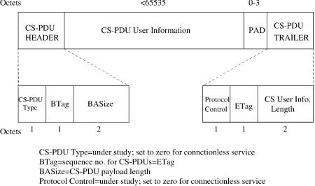
variable-length information units through the SAR sublayer. Figure A.30 shows the structure of the AAL 3r4 CPCS PDU. The CPCS-PDU header includes the fields common part identifier ŽCPI., beginning tag ŽBTA., and buffer allocation size ŽBSA., whereas the trailer includes the fields alignment ŽAL., ending tag ŽETA., and length ŽLEN.. CPI is used to interpret the subsequent fields in the CPCS-PDU header and trailer, for example the counting units of the subsequent fields BAS and LEN. BTA and ETA are equal in the same CPCS PDU. Different bytes are used in general for different CS PDUs, and the receiver checks the equality of BTA and ETA. BAS indicates to the receiver the number of bytes required to store the whole CPCS PDU. AL is used to make the trailer a 4-byte field, and LEN indicates the actual content of the PDU’s payload, whose length is up to 65,535 bytes. A padding field ŽPAD. is also used to make the payload an integer multiple of 4 bytes, which could simplify the receiver design. The current specification of CPI is limited to the interpretation just described for the BAS and LEN fields.
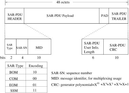
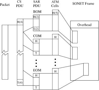
Figure A.31 shows the structure of the AAL 3r4 PDU. The segment type ŽST. is a 2-bit field that indicates a SAR-PDU as containing the beginning of a message ŽBOM., the continuation of a message ŽCOM., the end of a message ŽEOM., or a single-segment message ŽSSM.. The 4-bit sequence number ŽSN. field is used to number the SAR PDUs modulo 16 Ži.e., 0 to 15..
Fig. A.31 Structure of the AAL3r4 SAR PDU.
436 SONET AND ATM PROTOCOLS
Fig. A.32 Packet-cell conversion ŽAAL3r4..
The multiplexing identification ŽMID. field is 10 bits long and is used to multiplex different connections into a single ATM connection. All SAR PDUs of a particular connection are assigned the same MID value. Using this field, it is possible to interleave and reassemble SAR PDUs of different sources that are transported using the same VPIrVCI. Cells of different sources are distinguished by carrying different MID values. The 6-bit user information length indicates the number of bytes in the SAR PDU, and its value ranges from 4 to 44. A 10-bit CRC is used over the entire SAR PDU to detect bit errors. Figure A.32 shows how a data packet is converted to ATM cells Žusing AAL3r4. that are then embedded in SDH frames.
A.5.4 AAL Type 5
AAL5 is the most widely used AAL type to date. For instance, AAL5 is the adaptation layer for ILMI, UNI signaling, PNNI signaling, and for IP packets.
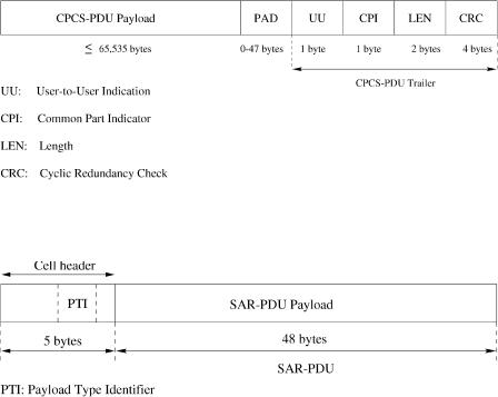
Figure A.33 shows the structure of AAL5 CPCS PDU. Its payload length can be from 1 to 65,535 bytes. A PAD field, ranging 0 to 47 bytes, is added to make the CPCS-PDU length an integer multiple of 48 bytes. Thus, it can completely fill in the SAR-PDU payloads. CPCS user-to-user indication ŽUU. is one byte long and may be used to communicate between two AAL5 entities. The common part indicator ŽCPI., also one byte long, is not defined
ATM ADAPTATION LAYER |
437 |
Fig. A.33 AAL5 CPCS-PDU format.
Fig. A.34 AAL5 SAR-PDU format.
yet and must be set to 0. LEN indicates the actual length of the CPCS-PDU payload, so as to identify the PAD size. A 32-bit CRC, following the FDDI standards, is used to detect bit errors in the CPCS PDU. The CPCS PDU is segmented into 48-byte SAR PDUs and passed to the ATM layer, where 5-byte cell headers are inserted to the front of the data units, as shown in Figure A.34.
The main reasons that AAL5 is the most widely used are its high utilization Žthe entire 48-byte payload is used to carry user’s information. and small processing overhead Žone CRC calculation for the entire CPCS PDU.. To have all 48 bytes carry user’s information, the ATM layer is required to indicate the last cell of a data packet to facilitate packet reassembly, which in turn violates the protocol stack. When a cell’s PTI is 000, it can be either a beginning of a message ŽBOM. or a continuation of a message ŽCOM.. When it is 001, the cell can be either an end of a message ŽEOM. or a single-seg- ment message ŽSSM.. A receiver will start to reassemble arriving cells when it receives the very first cell until it receives a cell with the PTI set to 001. Once an EOM or SSM is received, the receiver will start the reassembly process for the following packet.
438 SONET AND ATM PROTOCOLS
REFERENCES
1.ATM Forum, ‘‘User-Network Interface Specification Version 3.1,’’ ATM Forum Technical Committee, Sep. 1996.
2.ITU-T Recommendation G.707, ‘‘Network node interface for the synchronous digital hierarchy ŽSDH.,’’ Geneva, Nov. 1995.
3.ITU-T Recommendation I.432, ‘‘B-ISDN User Network Interface Specification,’’ Geneva, Aug. 1996.
4.R. Onvural, Asynchronous Transfer Mode Networks, Performance Issues, Artech House, Norwood, MA, 1995.
5.ITU-T Recommendation I.361, ‘‘B-ISDN ATM Layer Specification,’’ Geneva, Nov. 1995.
6.ITU-T Recommendation I.363, ‘‘B-ISDN ATM Adaptation Layer Specification,’’ Geneva, Mar. 1993.
7.ITU-T Recommendation I.363.1, ‘‘B-ISDN ATM Adaptation Layer Specification: Type 1 AAL,’’ Geneva, Aug. 1996.
8.ITU-T Recommendation I.363.2, ‘‘B-ISDN ATM Adaptation Layer Specification: Type 2 AAL,’’ Geneva, Sep. 1997.
9.J. H. Baldwin et al., ‘‘A new ATM adaptation layer for small packet encapsulation,’’ Bell Labs. Tech. J., pp. 111 131, Spring 1997.
10.ITU-T Recommendation I.363.3, ‘‘B-ISDN ATM Adaptation Layer Specification: Type 3r4 AAL,’’ Geneva, Aug. 1996.
11.ITU-T Recommendation I.363.5, ‘‘B-ISDN ATM Adaptation Layer Specification: Type 5 AAL,’’ Geneva, Aug. 1996.
12 ANSI T1.105, ‘‘SONET-Basic Description including Multiplex Structure, Rates, and Formats,’’ 1995.

INDEX
Abacus switch: architecture, 190 193
ATM routing and concentration chip, 208 211
enhanced configuration, 211 220 buffered multistage concentration
network, 214 217
complexity comparisons, 219 220 memoryless multistage concentration
network, 212 214 resequencing cells, 217 219
input port controller ŽIPC., 197 198 multicast contention resolution algorithm,
193 197
packet switching, 220 224 cell interleaving, 222 224
packet interleaving, 220 222 performance analysis, 198 208
average delay, 203 205
cell loss probability, 206 208 maximum throughput, 199 203
research issues, 189 190
Accept pointer, input-buffered switch scheduling:
iSLIP scheme, 60 62
iterative round-robin matching ŽiRRM., 60 Access point ŽAP.:
SONET protocols, section access point identifier, 414 417
wireless ATM ŽWATM. switches, 339
Access point control protocol ŽAPCP., wireless ATM ŽWATM. switches, 339 341
Acknowledgement ŽACK. packet format, wireless ATM ŽWATM. switches, data link control layer, 347
Adaptive homing algorithm, wireless ATM ŽWATM. switches, BAHAMA wireless ATM LAN, 343
AddPrefix Ž X, Y, Z . algorithm, internet protocol ŽIP. route lookups, two-trie structure, 399 402
Address broadcaster ŽAB.:
abacus switch, architecture, 191 193 fault-tolerant multicast output-
buffered ATM switch, fault detection, 173
multicast grouping networks ŽMGNs., 157 160
Address copy, multicast shared-memory switch, 99 101
Address filter ŽAF.:
bus matrix switch ŽBMX., buffering strategy, 26
multiple-QoS scalable distributedarbitration switch ŽMSDA., 235 236
time-division switching ŽTDS., shared-medium switch, 22 23
Address interval, broadcast banyan network ŽBBN., boolean interval spitting algorithm, 128 129
439
440 INDEX
Address queues, multicast shared-memory switch, 98 99
Alarm indication signal ŽAIS., SONET protocols, 419 421
All-optical packet switches: ATMOS, 282 283 Duan’s switch, 283 284
staggering switch, 281 282
ALOHA system, wireless ATM ŽWATM. switches:
medium access control layer, 346 Olivetti’s radio ATM LAN, 342 radio physical layer, 346
Application-specific integrated circuit ŽASIC.:
abacus switch architecture, 208 211 wireless ATM ŽWATM. switches,
mobility-support ATM switch, 354 358 Arbiter device:
abacus switch, multicast contention resolution algorithm, 194 197
optical interconnection network ŽOIN., ping-pong arbitration unit ŽPAU., 315 324
Arbitrating cells, input-buffered switches, output port contention, 49 50
Arbitration control ŽCNTL.: multiple-QoS scalable
distributed-arbitration switch ŽSDA., 234 236
scalable distributed-arbitration ŽMSDA. switch, 229 231
Arbitration schemes:
abacus switch, multicast contention resolution algorithm, 194 197 asynchronous transfer mode ŽATM.
switches, 16
Atlanta switches, distributedrrandom arbitration, 261 262
input-buffered switch:
dual round-robin matching ŽDRRM., 62 65
iterative round-robin matching ŽiRRM., 58 60
iterative round-robin with SLIP ŽiSLIP., 60 62
parallel iterative matching ŽPIM., 58 round-robin arbitersrselectors, 67 72 bidirectional arbiter ŽNTT., 67 70
token tunneling, 70 72
round-robin greedy scheduling ŽRRGS., 65 67
input-buffered switches, scheduling algorithms, 57
optical interconnection network ŽOIN., ping-pong arbitration unit ŽPAU., 316 324
Arrayed-waveguide grating ŽAWG. router, optical interconnection network ŽOIN., 309 315
crosstalk analysis, 329 331 tunable filters, 312 315
Asynchronous transfer mode ŽATM. switches. See also specific ATM switches, e.g., Wireless ATM
applications, 2 architecture:
buffering strategies, 34 37 classification, 21 37
design and performance criteria, 13 17 space-division switching ŽSDS., 24 34
multiple-path switches, 29 34 single-path switches, 25 29
time-division switching ŽTDS., 22 24 shared-medium switch, 22 23 shared-memory switch, 23 24
basic concepts, 15 17 call splitting, 20 24
head-of-line ŽHOL. blocking, 19 internal link blocking, 17 18 multicasting, 20 21
network basics, 35
optical ATMOS switch, 282 283 output port contention, 16 18 protocols:
background, 407 409 cell loss priority, 428 429 cell structure, 425 426
payload type identifier, 427 428 reference model, 409 410
virtual path and channel identifiers, 426 427
switch structure, 58 Atlanta switch:
architecture, 261 configuration, 259 261
distributed and random and arbitration, 261 262
multicasting, 262 263
ATM adaptation layer ŽAAL., asynchronous transfer mode ŽATM. network protocol, 408 409, 425 429
ATM routing and concentration ŽARC. chip, abacus switch, 208 211
ATM Wireless Access ŽAWA., wireless ATM ŽWATM. switches, 343
Automatic protection switching ŽAPS., SONET protocols, 419 421