

Broadband Packet Switching Technologies
.pdfSYNCHRONOUS OPTICAL NETWORK (SONET) |
421 |
Fig. A.15 AIS Žalarm indication signal. and RDI Žremove defect indication..
A.2.7 STS-3 vs. STS-3c
Superrate services, such as B-ISDN ATM service, require multiples of the STS-1 rate. They are mapped into an STS-Nc SPE and transported as a concatenated STS-Nc whose constituent STS-1s are lined together in fixed phase alignment. Figure A.16 shows the comparison of the STS-3 and STS-3c: the former is multiplexed from three STS-1 signals, while the latter is
Fig. A.16 STS-3 vs. STS-3c.
422 SONET AND ATM PROTOCOLS
Fig. A.17 STS-3c frame format.
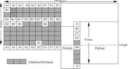
used to carry a single ATM cell stream. For the STS-3, there are three POHs, one for each STS-1 signal, while for the STS-3c there is only one POH. Thus, the number of bytes in the payload of the STS-3c frame is more than that of the STS-3 frame by 18 bytes.
Figure A.17 shows the frame structure of an STS-3c frame and the corresponding overhead bytes. Since there is only one SPE for each STS-3c frame, only one set of pointers ŽH1 and H2 bytes. in the LOH is used, while the other two sets ŽH1* and H2*. are not used. The entire STS-3c payload capacity Žexcluding SOH, LOH, and POH. can be filled with cells, yielding a transfer capacity for ATM cells of 149.760 Mbitrs Ž155.52 Mbitrs 260r270.. The remainder Ž5760 kbitrs. is available for the section, line, and path overhead. Because the STS-3c payload capacity Ž2340 bytes, or 260 9 bytes. is not an integer multiple of the cell length Ž53 bytes., a cell may cross a frame payload boundary.
A.2.8 OC-N Multiplexer
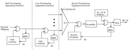
Figure A.18 shows how an OC-N signal is composed and where the functions associated with path-terminating equipment, line-terminating equipment, and section-terminating equipment are performed as the user’s payload passes through the path, line, and section layers. The user’s payload is first augmented with path overhead to form a SPE, and the B3 byte is calculated at the path layer. The SPE is then augmented with line overhead, and the B2 byte is calculated at the line layer. Finally, the resulting partial frame is multiplexed with byte interleaving and augmented with section overhead and the B1 byte is calculated. Note that the calculated B3, B2, and
SUBLAYER FUNCTIONS IN REFERENCE MODEL |
423 |
Fig. A.18 OC-N signal composition.
B1 bytes are placed at the corresponding positions in the next frame. Also note that the entire frame, except the framing bytes ŽA1 and A2. and the J0 byte, is scrambled.
A.3 SUBLAYER FUNCTIONS IN REFERENCE MODEL
The functions of the physical layer ŽU-plane. are grouped into the physical- medium-dependent ŽPMD. sublayer and the transmission convergence ŽTC. sublayer Žsee Fig. A.19.. The PMD sublayer deals with aspects that depend on the transmission medium selected. It specifies physical medium and transmission Že.g., bit timing, line coding. characteristics and does not include framing or overhead information.
The TC sublayer deals with physical layer aspects that are independent of the transmission medium characteristics. Most of the functions constituting the TC sublayer are involved with generating and processing some overhead bytes contained in the SONET frame. On transmission, the TC sublayer maps the cells to the frame format, generates the header error control ŽHEC, the last byte of the ATM cell header., and sends idle cells when the ATM layer has none to send. On reception, the TC sublayer delineates individual cells in the received bit stream, and uses the HEC to detect and correct received errors.
The HEC byte is capable of single-bit error correction and multiple-bit error detection. The transmitter calculates the HEC value across the entire ATM cell header and inserts the result in the HEC field. The value is the remainder of the division Žmodulo 2. by the generator polynomial x 8 q x 2 q x q 1 of the product x 8 multiplied by the contents of the header excluding
the HEC field. The remainder |
is added Žmodulo 2. to an 8-bit pattern3 |
3 When the first four bytes of the cell |
header are all zeros and the remainder is also zero, |
modulo-2 adding the 8-bit pattern to the remainder can reduce the length of the stream of zeros.
424 SONET AND ATM PROTOCOLS
Fig. A.19 Protocol reference model sublayers and functions.
Ž01010101. before being inserted in the HEC field. The receiver must subtract the same pattern from the 8-bit HEC before proceeding with the HEC calculation.
At the receiver two modes of operation are defined: correction mode and detection mode, as shown in Figure A.20. In correction mode only a single-bit error can be corrected, while detection mode provides for multiple-bit error detection. In detection mode all cells with detected errors in the header are discarded. When a header is examined and no error found, the receiver switches to correction mode.
Cell scramblingrdescrambling permits the randomization of the cell payload to avoid continuous nonvariable bit patterns and improve the efficiency of the cell delineation algorithm.
Fig. A.20 Receiver HEC bimodal operation.
ASYNCHRONOUS TRANSFER MODE |
425 |
Fig. A.21 Cell delineation state diagram.
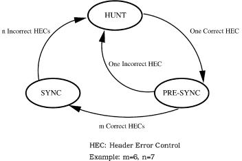
The cell delineation function identifies cell boundaries based on the HEC field. Figure A.21 shows the state diagram of the HEC cell delineation method. In the HUNT state, the delineation process is performed by checking for the correct HEC in the incoming data stream. Once a correct HEC has been detected, it is assumed that one cell header has been found, and the receiver passes to the PRE-SYNC state. In the PRE-SYNC state, the HEC checking is done cell by cell. The transition occurs from the PRE-SYNC state to the SYNC state if m consecutive correct HECs are detected, or to the HUNT state if an incorrect HEC is detected. In the SYNC state, the receiver moves to the HUNT state if n consecutive cells have an incorrect HEC. For instance, m can be 6 and n can be 7.
A.4 ASYNCHRONOUS TRANSFER MODE
The ATM layer provides for the transparent transfer of fixed-size ATM cells between communicating upper layer entities ŽAAL entities.. This transfer occurs on a preestablished ATM connection according to a traffic contract. A traffic contract is composed of a service class, a vector of traffic parameters Že.g., peak cell rate, sustainable rate, and maximum burst size., a conformance definition, and other parameters. Each ATM end system is expected to generate traffic that conforms to these parameters. Enforcement of the traffic contract is optional at the private UNI. The public network is expected to monitor the offered load and enforce the traffic contract.
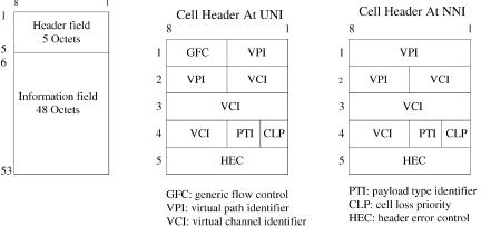
As shown in Figure A.22, an ATM cell has a 5-byte header field and a 48-byte information field. There are two types of cell headers, one for UNI
426 SONET AND ATM PROTOCOLS
Fig. A.22 ATM cell structure.
and one for the network-to-network interface ŽNNI.. The UNI cell header contains the following fields: 4-bit generic flow control ŽGFC., 8-bit virtual path identifier ŽVPI., 16-bit virtual channel identifier ŽVCI., 3-bit payload type identifier ŽPTI., 1-bit cell loss priority ŽCLP., and 8-bit header error control ŽHEC.. The NNI cell header does not have the GFC field, and its VPI field is 12 bits as opposed to 8 bits in the UNI cell header.
GFC can be used to provide local functions Že.g., flow control. on the customer site. It has local significance only; the value encoded in the field is not carried from end to end and will be overwritten by the ATM switches.
A.4.1 Virtual Path and Virtual Channel Identifiers
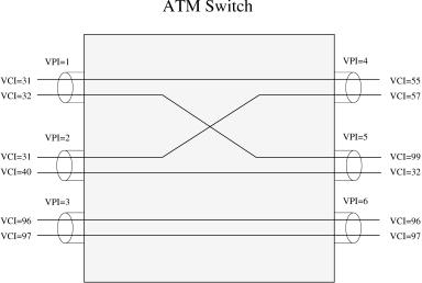
ATM has a two-level hierarchy of ATM connection, whereby a group of VCCs are usually bundled in a VPC. Within a transmission link, there can be multiple VPCs, and within each VPC there can be multiple VCCs. VPCs are logical ‘‘pipes’’ between any two ATM switch nodes that are not necessarily directly connected by a single physical link. Thus, it allows a distinction between physical and logical network structures and provides the flexibility to rearrange the logical structures according to the traffic requirements and end point locations. A VPC is often chosen to be a constant-rate ‘‘pipe’’; it is not restricted to be so, and it can belong to any of the service categories. For instance, a corporation might establish VPCs through a network service provider to interconnect various building locations. The presence of VPCs allows for quicker establishment of switched VCCs. The VPCs also enable faster restoration.
As shown in Figure A.23, when a VPC Že.g., VPI s 3. is routed by a switch node, only the VPI will be used to look up the routing table and be replaced with a new value ŽVPI s 6., and its VCI values remain unchanged ŽVCI s 96
ASYNCHRONOUS TRANSFER MODE |
427 |
Fig. A.23 Virtual paths and virtual channels.
and 97.. When a VCC Že.g., VPI s 2, VCI s 31. is routed through a switch, the combination of the VPI and VCI is used to look up the routing table and replaced with a new value ŽVPI s 4, VCI s 57. at the output link.
The two identifiers, together with the physical link the cells arrive from, uniquely identify connections at each ATM switch. At the UNI, there are 8 bits for the VPI, while at the NNI there are 12 bits. In general, VCI values are unique only at a particular VPI value, and VPI values are unique only in a particular physical link. The VPIrVCI has local significance only, and its value is replaced with a new value at a new physical link, which is known as label swapping. The reason for having the VPIrVCI change at every link is to support a large number of ATM end systems. For instance, the number of
hosts supported |
by IPv4 is limited to 232 , whereas in ATM the number |
is limited to 224 |
at UNI or 228 at NNI, per transmission link. |
A.4.2 Payload Type Identifier
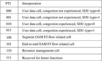
The main purpose of the payload type identifier ŽPTI. is to discriminate user cells Ži.e., cells carrying user information. from nonuser cells. As shown in Figure A.24, PTI values of 0 to 3 indicate user cells. PTI values of 2 and 3 indicate that congestion has been experienced in the network. PTI values of 4 and 5 are used for VCC level management functions ŽF5 flow., where OAM cells of F5 flow have the same VPIrVCI value as the user data cells transported by the VCC. A PTI value of 4 is used for identifying OAM cells communicated within the bounds of a VCC segment Ži.e., a single link segment across the UNI., while a PTI value of 5 is used for identifying
428 SONET AND ATM PROTOCOLS
Fig. A.24 Payload type identifier ŽPTI. encoding.
end-to-end OAM cells. A PTI value of 6 indicates the resource management ŽRM. cell.
A congestion flow control scheme used in the ATM network is explicit forward congestion notification. When a network node detects congestion on the link, it will mark the congestion-experienced bit in the PTI of user data cells passing through the congested link Ži.e., changing the pattern 000 to 010, or 001 to 011.. Once a cell is marked congestion-experienced at a node, it cannot be modified back to congestion-not-experienced by any downstream node along the path to the destination node. The receiver can set a congestion indication bit in the RM cells to instruct the sender to slow down, increase, or maintain the rate. The RM cells are normally transmitted from the sender to the receiver every certain number of data cells it sends.
A.4.3 Cell Loss Priority
The CLP field may be used for loss priority indication by an ATM end system and for selective cell discarding in network equipment. This bit in the ATM cell header indicates two levels of priority for ATM cells. Cells with CLP s 0 are higher priority than those with CLP s 1. Cells with CLP s 1 may be discarded during periods of congestion to preserve the loss rate of the cells with CLP s 0.
A.4.4 Predefined Header Field Values
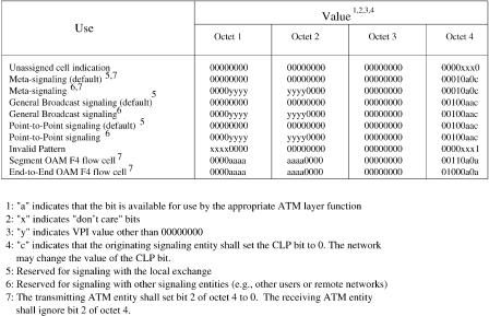
Figure A.25 shows some predefined header field values.The cell rate decoupling function at the sending entity adds unassigned cells to the assigned cell stream Žcells with valid payload. to be transmitted. In other words, it transforms a noncontinuous stream of assigned cells into a continuous stream
ATM ADAPTATION LAYER |
429 |
Fig. A.25 Predefined header field values.
of assigned and unassigned cells. At the receiving entity, the opposite operation is performed for both unassigned and invalid cells. The rate at which the unassigned cells are inserted or extracted depends on the bit rate Žrate variation. of the assigned cell andror the physical layer transmission rate.
Meta-signaling cells are used by the meta-signaling protocol for establishing and releasing SVCs. For PVCs, meta-signaling is not used.
The virtual path connection ŽVPC. operation flow ŽF4 flow. is carried via specially designated OAM cells. The OAM cells of the F4 flow have the same VPI value as the user-data cells transported by the VPC but are identified by two unique preassigned virtual channels within this VPC. At the UNI, the virtual channel identified by a VCI value 3 is used for virtual-path level management functions between ATM nodes on both sides of the UNI Ži.e., single virtual-path link segments., while the virtual channel identified by a VCI value 4 can be used for virtual path level end-to-end management functions.
A.5 ATM ADAPTATION LAYER
The AAL performs the functions necessary to adapt the capabilities provided by the ATM layer to the needs of higher-layer applications. Since the ATM layer provides an indistinguishable service, the AAL is capable of providing
430 SONET AND ATM PROTOCOLS
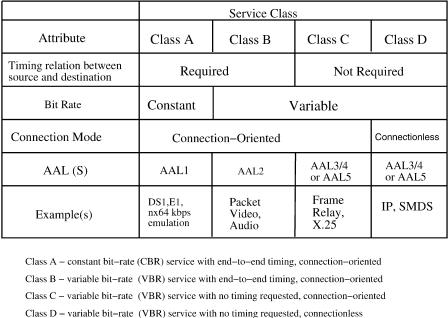
Fig. A.26 ITU ATMrB-ISDN service classes.
different functions for different service classes. For instance, VBR users may require such functions as protocol data unit ŽPDU. delineation, bit error detection and correction, and cell loss detection. CBR users typically require source clock frequency recovery, and detection and possible replacement of lost cells. These services are classified by ITU-T based on three parameters: timing relationship between source and destination, bit rate, and connection mode. Four classes have been defined and shown in Figure A.26.
Class A: This class corresponds to CBR, connection-oriented services with a timing relationship between source and destination. Typical services of this class are voice, circuit emulation, and CBR video.
Class B: This class corresponds to VBR Žvariable bit rate. connectionoriented services with a time relationship between source and destination. Packet video is a typical example of this service class.
Class C: This class corresponds to VBR connection-oriented services with no timing relationship between source and destination. X.25 and frame relay are typical examples of this service class.
Class D: This class corresponds to VBR connectionless services with no timing relationship between source and destination. IP data transfer is a typical example of this type of service.