

Broadband Packet Switching Technologies
.pdfSYNCHRONOUS OPTICAL NETWORK (SONET) |
411 |
addrdrop multiplexer ŽADM., and digital cross-connect system ŽDCS.. In practical applications, the communication is bidirectional. Let us consider an example where non-SONET transmission signals from the left are multiplexed by a SONET MUX terminal into SONET frames that are converted to optical signals. Due to attenuation and dispersion in optical fibers, the SONET bit stream needs to be regenerated: the optical signal is first converted to the electrical signal, which is amplified, resampled, and then
Fig. A.4 SONET end-to-end connection.
Fig. A.5 SONET layers and associated overheads.
412 SONET AND ATM PROTOCOLS
converted back to the optical signal. Because of the resampling, a phase-lock loop circuit is required to recover the clock from the incoming bit stream. The ADM is used to add and drop one or several low-rate tributaries, while the DCS is used for rerouting or grooming low-rate tributaries.
Section is the portion of the SONET connection between a terminal and a regenerator, or between two regenerators. Line is the portion of the connection between a MUX terminal and an ADMrDCS, or between ADMsrDCSs. Path, related to services, is a logical connection between two end terminals, where SONET frames are generated by one terminal and removed by the other. As shown in Figure A.5, each portion of the SONET connection has overhead bytes to facilitate operation, administration, and maintenance ŽOAM. functions in the corresponding portion of the SONET connection. For instance, messages from the service layer Že.g., DS1, DS3, or video streams. accumulate path overhead ŽPOH., line overhead ŽLOH., and section overhead ŽSOH. as they are passed down to different layers in SONET. At the receiver end, these overheads are stripped off as the messages are passed up to the service layer.
A.2.2 STS-N Signals
The basic SONET transmission signal is synchronous transfer signal level 1 ŽSTS-1., and its transmission frame is shown in Figure A.6. Each frame has 810 bytes and is organized into 9 rows of 90 bytes Žtransmitted from left to right, top to bottom.. Frames are repeated every 125 s, corresponding to 8-kHz voice sampling rate. The bit rate of the STS-1 is Ž810 bytes.rŽ125 s., or 51.84 Mbitrs. The first three columns Ž27 bytes. are reserved for transport overhead, consisting of 9-byte SOH and 18-byte LOH. The remaining 87 columns form an STS-1 synchronous payload envelope ŽSPE., where the first column is reserved for POH.
As shown in Figure A.6, an SPE does not need to be aligned to a single STS-1 frame. In other words, it may ‘‘float’’ and occupy parts of two consecutive frames. There are two bytes in LOH used as a pointer to indicate the offset in bytes between the pointer and the first byte of the SPE.
When N STS-1 signals are multiplexed with byte interleaving into an STS-N signal, the STS-N frame structure is as shown in Figure A.7. The byte position in STS-1 is now ‘‘squeezed’’ with N bytes of information, either overhead bytes or user’s data. For instance, the first two bytes of STS-1 are A1 and A2 bytes for framing. Now, there are N bytes of A1 followed by N bytes of A2 in STS-N frames. The STS-N frames also repeat every 125 s, and the bit rate of the STS-N signal is N times that of the STS-1 signal.
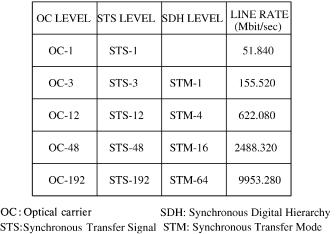
Certain values of N have been standardized, and their corresponding bit rates are shown in Figure A.8. SONET is standardized by the American National Standards Institute ŽANSI. and is deployed in North America, while Synchronous Digital Hierarchy ŽSDH. is standardized by ITU-T and is deployed in the other parts of the world. SONET and SDH are technically

SYNCHRONOUS OPTICAL NETWORK (SONET) |
413 |
Fig. A.6 Two STS-1 Žsynchronous transfer signal level 1. frames.
Fig. A.7 Synchronous transfer signal level N ŽSTS-N . frames.
414 SONET AND ATM PROTOCOLS
Fig. A.8 Standardized SONET SDH rates.
consistent. The major difference between them is in their terminologies. Figure A.8 shows the mapping between them. Synchronous transfer mode level 1 ŽSTM-1. is the basic transmission signal in SDH, and its bit rate is 155.52 Mbitrs. Higher-capacity STMs are formed at rates equivalent to m times this basic rate. STM capacities for m s 4, m s 16, and m s 64 are defined and called STM-4, STM-16, and STM-64. Their corresponding rates are shown in Figure A.8. The optical format of the STS-N signal is called optical carrier level N ŽOC-N ..
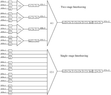
Figure A.9 shows two examples of multiplexing 12 STS-1 signals into an STS-12 signal, one with two stages of multiplexing and one with a single stage. In order to have identical byte streams at the output of the multiplexer, it has been standardized that the output byte stream has to be the same as the one from multiplexing multiple STS-3 signals.
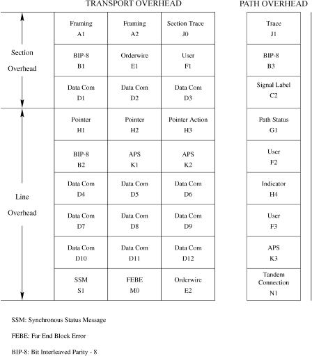
A.2.3 SONET Overhead Bytes
Figure A.10 shows the section, line, and path overhead bytes. A1 Ž11110110. and A2 Ž00101000. are used for frame alignment. In order to reduce the probability of having A1 and A2 bytes in the payload frame and to avoid a long stream of 0s and 1s, the entire frame except the first 9 bytes is scrambled Žsee Section A.2.4.. The J0 byte is allocated to a section trace. This byte is used to transmit repetitively a section access point identifier so that a section receiver can verify its continued connection to the intended transmitter. B1 is used to monitor the error in the regenerator section. B1 is computed using bit-interleaved even parity over all the bits of the previous
SYNCHRONOUS OPTICAL NETWORK (SONET) |
415 |
Fig. A.9 Example of byte interleaving.
STS-1 frame after scrambling and is placed in byte B1 of the current frame before scrambling. The E1 byte is allocated in the first STS-1 of an STS-N signal for a 64-kbitrs orderwire channel used for voice communication between regenerators and terminal locations. The F1 byte is allocated in the first STS-1 of an STS-N signal and is reserved for user purposes Že.g., to provide temporary datarvoice channel connections for special maintenance purposes.. The D1 D3 bytes are located in the first STS-1 of an STS-N signal for section data communication. These three bytes form a 192-kbitrs message-based channel for alarms, maintenance, control, monitoring, administering, and other communication needed between section-terminating equipment.
The pointer, ŽH1 and H2 bytes., is used to find the first byte of the SPE. When their value is zero, the SPE starts immediately following the H3 byte. H3 is used for frequency justification to compensate for clock deviations between the source and the multiplexer terminals, which may occur in some circumstances Žsee Section A.2.5.. The B2 bytes are used to monitor bit
416 SONET AND ATM PROTOCOLS
Fig. A.10 Section, line, and path overhead bytes.
errors at the multiplexer section. It is computed using bit-interleaved even parity over all bits of the previous STS-1 frame except for the first three rows of SOH and is placed in bytes B2 of the current frame before scrambling. The K1, K2, and M0 bytes are related to automatic protection switching ŽAPS. operations Žsee Section A.2.6.. The D4 D12 bytes form a 576-kbitrs channel available at the line terminating equipment. The S1 byte is allocated for the synchronous status message ŽSSM. function. It indicates the type of clock generating the synchronization signal. The M0 byte is allocated for the far end block error ŽFEBE. function, which is assigned for the Nth STS-1 of
SYNCHRONOUS OPTICAL NETWORK (SONET) |
417 |
an STS-N signal. The E2 byte provides an orderwire channel of 64 kbitrs for voice communication between line-terminating equipment.
The J1 byte is used to transmit repetitively a path access point identifier so that a path receiving terminal can verify its continued connection to the intended transmitter. The B3 byte is allocated for a path error monitoring function. It is calculated using bit-interleaved even parity over all bits of the previous frame payload before scrambling and is placed at the B3 byte location of the current frame payload before scrambling. Bits 1 4 of the G1 byte convey the count of interleaved-bit blocks that have been detected in error Žranging from 0 to 8.. This error count is obtained from comparing the calculated parity result and the B3 byte value of the incoming frame. The F2 and F3 bytes are allocated for user communication purposes between path elements and are payload-dependent. The H4 byte provides a generalized position indicator for payloads and can be payload-specific. Bits 1 4 of the K3 byte are allocated for APS signaling for protection at the path levels. The N1 byte is allocated to provide a tandem connection monitoring ŽTCM. function. The tandem connection sublayer is an optional sublayer that falls between the multiplex section and path layers and is application-specific.
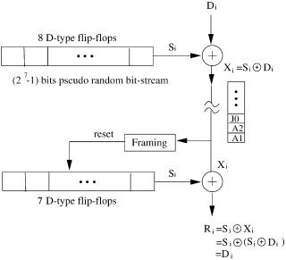
A.2.4 Scrambling and Descrambling
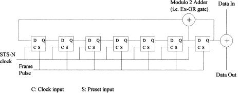
Figure A.11 shows how scrambling and descrambling are done in SONET. A pseudo-random bit stream with 27 y 1 bits is generated by a shift register Žseven D-type flip-flops. with some feedback lines as shown in Figure A.12.
Fig. A.11 Frame-synchronous scrambling.
418 SONET AND ATM PROTOCOLS
Fig. A.12 Circuit of the frame-synchronous scrambler.
The pseudo-random bit stream ŽSi . is then exclusive-ORed with the data bit stream Ž Di .. The scrambled bitstream Ž Xi . is sent to the network and is descrambled with the same pseudo-random bit stream. If no error occurs in the network, the received bit stream Ž Ri . will be obtained by exclusive-ORing Ri with Si. To synchronize the pseudo-random bitstreams at the transmitter and the receiver, the pseudo-random bitstream generators Žthe shift registers. are both reset to all ones by a frame pulse that is generated from the detection of framing bytes ŽA1 and A2.. The scramble generating polynomial is 1 q X 6 q X 7, resulting in the outputs of the two D-type flip-flops on the right Žcorresponding to X 6 and X 7 . being exclusive-ORed and fed back to the input of the shift register.
A.2.5 Frequency Justification
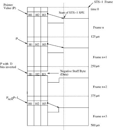
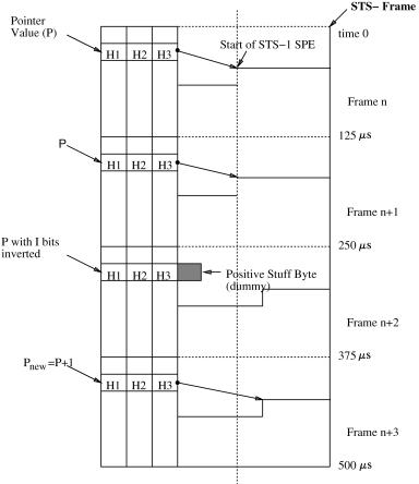
The pointer bytes of all STS-1 signals within an STS-N signal are to align the STS-1 transport overheads in the STS-N signal as well as perform frequency justification. When multiplexing a user’s data to STS-1 frames, if the user’s data rate is higher than the STS-1 payload bandwidth, negative frequency justification occurs. That is, on occasion, one extra byte is added to the payload, as shown in Figure A.13. This is done by inverting the 5 bits of the H1 and H2 bytes in the D Ždecrement. positions for frame n q 2 and then decrementing the pointer by 1 in frame n q 3. As a result, SPE n q 3 starts sooner with the extra byte placed at the H3 byte location. The reason not to immediately decrement the pointer value by one is to avoid misinterpretation of the pointer value due to bit error. By inverting the five D bits of the pointer, it can tolerate up to two bit errors. On the other hand, when the user’s data rate is lower than the STS-1 payload bandwidth, positive justification occurs. That is, on occasion, one byte is not made available to the payload. As shown in Figure A.14, this is done by inverting the five I Žincrement. bits in the H1 and H2 bytes in frame n q 2 and then increment-
SYNCHRONOUS OPTICAL NETWORK (SONET) |
419 |
Fig. A.13 Negative STS-1 pointer justification.
ing the pointer by 1 in frame n q 3. As a result, SPE n q 3 starts later. The byte next to H3 is now left empty or ‘‘stuffed’’ and not allowed to be part of the SPE.
A.2.6 Automatic Protection Switching (APS)
Two types of maintenance signals are defined for the physical layer to indicate the detection and location of a transmission failure. These signals the alarm indication signal ŽAIS. and remote defect indication ŽRDI.
are applicable at the section, line, and path layers of the physical layer. An AIS is used to alert associated termination points in the direction of transmission that a failure has been detected and alarmed. A RDI is used to alert associated termination points in the opposite direction of transmission that a defect has been detected. As shown in Figure A.15Ža., when a fiber is cut or
420 SONET AND ATM PROTOCOLS
Fig. A.14 Positive STS-1 pointer justification.
the transmission equipment fails, an AIS is generated and transmitted in the downstream direction with respect to terminal A, while a RDI is generated for the upstream direction. If failures occur at both directions as shown in Figure A.15Žb., the AIS and RDI are generated and transmitted in both directions.
K1 and K2 bytes are allocated for APS signaling for the protection of the SONET equipment. For instance, line AIS is generated by inserting a 111 code in positions 6, 7, and 8 of the K2 byte in the downstream direction, whereas line RDI is generated by inserting a 110 code inpositions 6, 7, and 8 of the K2 byte in the upstream direction. The M0 byte is used to convey the count of interleaved bit blocks that have been detected in error in the range w0, 24x. This error count, obtained from comparing the calculated parity result and the B2 value of the incoming signal at the far end, is inserted in the M0 field and sent back. It reports to the near end line-terminating point about the error performance of its outgoing signal.