

Broadband Packet Switching Technologies
.pdf400 IP ROUTE LOOKUPS
Žb. The mismatch is detected on the rear trie.
i.At the rear node where the mismatch is detected, let the variable M be the K-bit part of the prefix in the structure that differs from that of the prefix X. Note that M is the value that causes the occurrence of the mismatch.
ii.Retrieve the length and the next hop at the separate node we just visited, and copy it into the variables L and N. Change this separate node into a front node.
iii.Create new front nodes on the front trie for matching the parts of the prefix X the algorithm already visited on the rear trie from the first rear node visited to the rear node where the mismatch was detected.
iv.Create a new separate node next to the front states in step 3Žb.iii for matching the value M. Set a linkage of this node with the rear trie. Store the values of L and N into this separate node.
v.Add the necessary parts of the new prefix X and its length and next hop into the two-trie structure by doing steps 3Ža.i to 3Ža.iii.
vi.Remove all unused nodes from the rear trie.
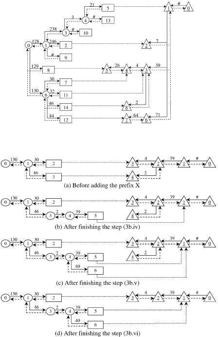
Suppose that we would like to add a prefix X s ²130.46.2.39. : of length Y s 32 bits and the next hop Z into the structure in Figure 13.29. The traversal starts from the root node of the front trie, matches 130, and moves to the node 6. At the node 6, a mismatch is detected on the front trie. The function creates a new separate node 14 for matching 46 and stores the length Y and the next hop Z at this node. The remaining part of X, which is ²2.39. :, is checked with the rear trie. From the root node of the rear trie, the traversal passes the nodes 1 and 3 for matching and 39. At the node 3, a new rear node 8 is created for matching 2. Finally, a linkage is set to connect the separate node 14 with the rear node 8. The final result of the algorithm is illustrated in Figure 13.31.
Now let us consider another example. Suppose that we would like to add a prefix X s ²130.46.2.40. : of length Y s 32 bits and the next hop Z into the structure in Figure 13.32Ža.. The traversal starts from the root node of the front trie, and finally a mismatch is detected at the rear node 2. Copy the value 39 into M. The length and the next hop of the prefix ²130.46.2.39. : stored at the separate node 3 is copied into L and N. Change the status of the node 3 from the separate node into a front node. Now create the front node 4 and the separate node 5 for matching 2 and M Žwhich is 39.. Store the values L and N into the separate node 5, and set a linkage to connect the node 5 with the rear node 1. The result is shown in Figure 13.32Žb.. Add the necessary parts of X by creating a new separate node 6 for matching 40, traversing the rear trie from the root node for matching , stopping at the
IP ROUTE LOOKUPS USING TWO-TRIE STRUCTURE |
401 |
Fig. 13.31 The result of adding the prefix X s ²130.46.2.39. : into the two-trie structure in Figure 13.29. Ž 1999 IEEE..
Fig. 13.32 Illustration of adding of the prefix X s ²130.46.2.40. :. Ž 1999 IEEE..
402 IP ROUTE LOOKUPS
node 1, setting a linkage to connect the separate node 6 and the rear node 1. The result is shown in Figure 13.32Žc.. Remove the unused node 4 from the rear trie. The final result of the function is shown in Figure 13.32Žd..
Algorithm DelPrefix( X, Y )
1.Start by traversing nodes from the root node of the front trie to the root node of the rear trie to check whether the prefix X is in the structure.
2.If X is not in the structure, the algorithm stops.
3.If X is in the structure, the traversal finally reaches the root node of the rear trie. The current length of X retrieved from the separate node we just visited along the path is compared with the length Y. If they are equal, the algorithm searches for the second longest prefix from the structure and replaces the length and the next hop of X with the ones of this prefix. If we cannot find the second longest prefix, we do the
prefix deletion by performing the following steps:
Ža. Remove the separate node we just visited during the traversal, and
destroy the linkage that connects it with the rear trie. Žb. Remove unused nodes from the rear trie.
Žc. Rearrange the two-trie structure to maintain the property that the separate nodes are the nodes that differentiate a prefix from other prefixes.
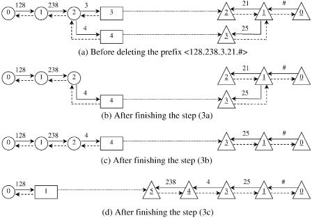
Fig. 13.33 Illustration of deleting the prefix ²128.238.3.21. :. Ž 1999 IEEE..
IP ROUTE LOOKUPS USING TWO-TRIE STRUCTURE |
403 |
Suppose that we would like to delete the prefix ²128.238.3.21. : from the structure shown in Figure 13.33Ža.. We do the deletion operation by removing the separate node 3 and the linkage connecting the node 2, as shown in Figure 13.33Žb.. The unused node 2 is removed from the rear trie, as in Figure 13.33Žc.. Then the two-trie structure is rearranged in that the prefix ²128.238.4.25. : should be differentiated by using the node 1 instead of the node 4. The final result of the operation is shown in Figure 13.33Žd..
13.9.3Performance
In this section, we will discuss the performance of our scheme based on program simulation. For performance measurement, we used a practical routing table with over 38,000 prefixes obtained from w11x. Two performance issues are considered: Ž1. the number of memory accesses taken for the lookup operation, and Ž2. the memory space required for the two-trie structure.
The worst case of the lookup operation for the 8-bit two-trie structure occurs when, for example, the IP destination address ²128.238.3.21. : is searched for the next hop in Figure 13.29. The lookup operation takes one memory access at the root node to transfer to the node 1. At the nodes 1, 3, and 4, it takes three memory accesses for each level: two for updating the next hop value to be that of the longer prefix, and one for transferring to the next level. At the separate node 5, the algorithm reaches the last part of the address which is 21. It takes one more memory access to retrieve the next hop value. Thus, the total number of memory accesses in the worst case is 11. The performance of the lookup operation can, however, be improved by modifying the value of K at the first level of the two-trie structure so that the root node of the front trie covers 16 bits of the prefixes. In such a case, the number of levels at the front trie is reduced by one and the total number of memory accesses in the worst case is reduced to 8.
The number of memory accesses for a lookup operation in the worst case can be reduced to 4 if we eliminate all separate nodes and put the next-hop information into the front nodes. By doing this, each entry in the front node has two more fields: one stores the next-hop information, and the other stores the pointer to the corresponding rear node. This increases the size of the front nodes and, in turn, the memory requirements of the structure; that is the price of the faster lookup operation.
To find the IP lookup performance on the average, assuming that the IP addresses are equally probable, we generated 100 million addresses and performed the lookup operations for them. For the sake of comparison, we used the 8-bit trie structure. The result is shown in Table 13.2.
A typical implementation can be used to implement the two-trie structure. The front or the rear node contains one pointer to its parent node and the entries providing the associated pointers to the nodes at the next level. The separate node stores the length and the next-hop information of each prefix. It also stores two pointers for each direction. Additionally, each node in the
404 |
IP ROUTE LOOKUPS |
|
|
|
TABLE 13.2 The Number of Memory Accesses for the Lookup Operation |
||||
|
|
|
|
|
|
Structure |
|
Bits for Each Level |
Average Case |
|
|
|
|
|
|
Two-trie |
|
8, 8, 8, and 8 |
3.6 |
|
Two-trie |
|
1, 6, 8, and 8 |
1.6 |
|
Standard trie |
|
8, 8, and 8 |
2.1 |
|
|
|
|
|
TABLE 13.3 Memory Requirements for the Structures after Creating the Routing Table with 38,000 Routing Entries
Structure |
Bits for Each Level |
Memory Requirements ŽMbyte. |
|
|
|
Two-trie |
8, 8, 8, and 8 |
11.6 |
Two-trie |
16, 8, and 8 |
11.6 |
Standard trie |
8, 8, and 8 |
16.0 |
|
|
|
structure contains other necessary node information for use while performing the prefix addition and deletion.
To build up the two-trie structure, we read each IP route from the practical routing table in random order and performed the prefix addition. The result is shown in Table 13.3.
By using the two-trie structure to implement the routing table, we can reduce the memory by around 27% in comparison with the standard trie.
REFERENCES
1.J. Aoe, K. Morimoto, M. Shishibori, and K. Park, ‘‘A trie compaction algorithm for a large set of keys,’’ IEEE Trans. Knowledge Data Eng., vol. 8, no. 3,
pp. 476 490, 1996.
2.M. Degermark, A. Brodnik, S. Carlsson, and S. Pink, ‘‘Small forwarding tables for fast routing lookups,’’ Proc. ACM SIGCOMM ’97, Cannes, France, pp. 3 14, Sep. 1997.
3.W. Doeringer, G. Karjoth, and M. Nassehi, ‘‘Routing on longest-matching prefixes,’’ IEEErACM Trans. Networking, vol. 4, no. 1, Feb. 1996.
4.V. Fuller, T. Li, J. Yu, and K. Varadhan, ‘‘Classless inter-domain routing ŽCIDR.: an address assignment and aggregation strategy,’’ RFC 1519, Internet Engineering Task Force, Sep. 1993.
5.P. Gupta, S. Lin, and N. McKeown, ‘‘Routing lookups in hardware at memory access speeds,’’ Proc. IEEEINFOCOM ’98, San Francisco, pp. 1240 1247, Apr. 1998.
6.N. Huang, S. Zhao, J. Pan, and C. Su, ‘‘A fast IP routing lookup scheme for gigabit switching routers,’’ Proc. IEEE INFOCOM ’99, New York, Mar. 1999.
7.T. Kijkanjanarat and H. J. Chao, ‘‘Fast IP lookups using a two-trie data structure,’’
Proc. IEEE Globecom ’99, 1570 1575, 1999.
REFERENCES 405
8.D. Knuth, Fundamental Algorithms. Vol. 3: Sorting and Searching, AddisonWesley, 1973.
9.B. Lampson, V. Srinivasan, and G. Varghese, ‘‘IP lookups using multiway and multicolumn search,’’ Proc. IEEE INFOCOM ’98, San Francisco, pp. 1248 1256, Apr. 1998.
10.D. R. Morrison, ‘‘PATRICIA practical algorithm to retrieve information coded in alphanumeric,’’ J. ACM, vol.17, no. 1, pp. 1093 1102, Oct. 1968.
11.Merit Network, Inc. http:rrwww.merit.eduripma.
12.S. Nilsson and G. Karlsson, ‘‘Fast address lookup for internet routers,’’ Proc. IFIP 4th Int. Conf. on Broadband Communication, Stuttgart, Germany, pp. 11 22, Apr. 1998.
13.C. Partridge, P. Carvey, E. Burgess, I. Castineyra, T. Clarke, L. Graham, M. Hathaway, P. Herman, A. King, S. Kohlami, T. Ma, T. Mendez, W. Milliken, R. Osterlind, R. Pettyjohn, J. Rokosz, J. Seeger, M. Sollins, S. Storch, B. Tober,
G. Troxel, D. Waitzman, and S. Winterble, ‘‘A fifty gigabit per second IP router,’’
IEEErACM Trans. Networking, vol. 6, no. 3, Jun. 1998.
14.V. Srinivasan, and G. Varghese, ‘‘Faster IP lookups using controlled prefix expansion,’’ Proc. ACMSIGMATICS ’98, Madison, WI, pp. 1 10, Jun. 1998.
15.H.-Y. Tzeng, ‘‘Longest prefix search using compressed trees,’’ Proc. of IEEE GLOBECOM ’98, Sydney, Australia, Nov. 1998.
16.M. Waldvogel, G. Varghese, J. Turner, and B. Plattner, ‘‘Scalable high-speed IP routing lookups,’’ Proc. ACM SIGCOMM ’97, Cannes, France, pp. 25 36, Sep. 1997.

Broadband Packet Switching Technologies: A Practical Guide to ATM Switches and IP Routers
H. Jonathan Chao, Cheuk H. Lam, Eiji Oki
Copyright 2001 John Wiley & Sons, Inc. ISBNs: 0-471-00454-5 ŽHardback.; 0-471-22440-5 ŽElectronic.
APPENDIX
SONET AND ATM PROTOCOLS
The asynchronous transfer mode ŽATM. was standardized by the International Consultative Committee for Telephone and Telegraphy ŽCCITT., currently called International Telecommunications Union Telecommunication ŽITU-T., as the multiplexing and switching principle for the Broadband Integrated Services Digital Network ŽB-ISDN.. The ATM is a connectionoriented transfer mode based on statistical multiplexing techniques. It is asynchronous in the sense that the recurrence of cells containing information from an individual user is not necessarily periodic. It is capable of providing high-speed transmission with low cell loss, low delay, and low delay variation. It also provides flexibility in bandwidth allocation for heterogeneous services ranging from narrowband to wideband services Že.g., video on demand, video conferencing, video-phone, and video library..
ATM connections either are preestablished using management functions or are set up dynamically on demand using signaling, such as user-network interface ŽUNI. signaling and private network network interface ŽPNNI. routing signaling. The former are referred to as permanent virtual connections ŽPVCs., while the latter are referred to as switched virtual connections ŽSVCs..
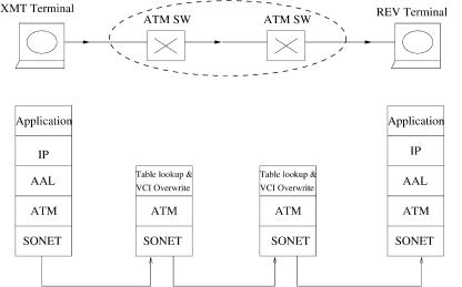
As shown in Figure A.1, two ATM end systems communicate through two ATM switches. The left end system sends messages generated at the application layer to the right one. The messages are first carried in IP packets,1 which are then passed down to different layers below the IP layer. Control bytes are added at different layers to facilitate the communications through
1 In native ATM applications, messages can be directly carried by ATM cells without first being carried by IP packets.
407
408 SONET AND ATM PROTOCOLS
Fig. A.1 Protocol layers in the synchronous optical network ŽSONET. ATM network.
the ATM network. At the receiver, the control bytes are stripped off before the final messages are recovered at the application layer Žif no error occurs during the transmission.. Inside the ATM network, there are only two layers, the physical layer we.g., the Synchronous Optical Network ŽSONET.x and the ATM layer, while at the end systems an additional layer wATM adaptation layer, ŽAAL.x is added. ATM cells are routed through the ATM switches based on the routing information inside the cell header Ž5 bytes.. The routing tables in every switch node on the path are updated either statically for PVCs or dynamically for SVCs. Once the routing tables are all updated, the connection between the two end systems is established and the left one can start to send traffic.
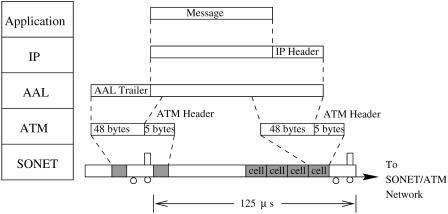
The detailed protocol conversion between the layers is shown in Figure A.2. A message generated at the application layer is passed down to the IP layer, where a 20-byte IP header is added. At the AAL, some AAL trailer overhead bytes are added and segmented into fixed-length data units Že.g., 48 bytes per unit.. They are then passed down to the ATM layer, where a 5-byte cell header is added to every cell. A series of cells is then put into the payload of SONET frames, which repeat every 125 s. Here, SONET frames can be likened to trains, and their overhead bytes to train engines.2 Cells are like cars in the trains. Cars in the trains may go to different destinations. As the trains arrive at a train station Ži.e., an ATM switch., train engines are removed and cars are routed to different tracks Ži.e., output links
2 The overhead bytes are actually evenly distributed in the SONET frame. For easy explanation, they are lumped together here.
ATM PROTOCOL REFERENCE MODEL |
409 |
Fig. A.2 Conversion between protocol layers.
of the switch. for which the cars are destined. These cars are packed together with others into trains that go to the same train station.
Section A.1 describes the ATM protocol reference model. Section A.2 describes SONET transmission frames and the functions related to the overhead bytes. Section A.3 describes the functions performed in different sublayers of the reference model. Section A.4 describes the ATM cell format and the related functions performed in the ATM layer. Section A.5 describes different AAL types Ž1, 2, 3r4, and 5..
A.1 ATM PROTOCOL REFERENCE MODEL
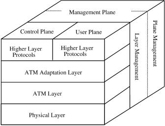
The ATM protocol reference model shown in Figure A.3 specifies the mapping of higher-layer protocols onto AAL, ATM, and its underlying physical layer. It is composed of four layers and three planes Žuser, control, and management planes..
U-plane: The user plane provides for the transfer of user application information. It contains the physical layer, the ATM layer, and multiple
ATM adaptation layers required for different service users, e.g.,con- stant-bit-rate ŽCBR. and variable-bit-rate ŽVBR. services.
C-plane: The control plane protocols deal with call establishment and release and other connection control functions necessary for providing switched services. The C-plane structure shares the physical and ATM layers with the U-plane. It also includes AAL procedures and higher-
layer signaling protocols, such as integrated local management interface ŽILMI., UNI signaling, and PNNI routing protocols.
410 SONET AND ATM PROTOCOLS
Fig. A.3 ATM protocol reference model.
M-plane: The management plane provides management functions and the capability to exchange information between the U-plane and C-plane.
The ILMI protocol uses the simple network management protocol ŽSNMP. to provide ATM network devices with status and configuration information concerning virtual path connections ŽVPCs., virtual channel connections ŽVCCs., registered ATM addresses, and the capabilities of ATM interfaces. UNI signaling specifies the procedures for dynamically establishing, maintaining, and clearing ATM connections at the UNI. The procedures are defined in terms of messages and the information elements used to characterize the ATM connection and ensure interoperability. The PNNI protocol provides the functions to establish and clear such connections, efficiently manage the resources of the network, and allow networks to be easily configured.
A.2 SYNCHRONOUS OPTICAL NETWORK (SONET)
ATM cells can be carried on different physical layers, such as digital signal level 1 ŽDS1., DS3, SONET, and others. Here, we only discuss how cells are carried in SONET transmission frames. SONET is a digital transmission standard based on the synchronous rather than the plesiochronous multiplexing scheme.
A.2.1 SONET Sublayers
Figure A.4 shows a SONET end-to-end connection with some typical SONET equipment, such as SONET multiplexer ŽMUX. terminal, regenerator,