

Broadband Packet Switching Technologies
.pdf390 IP ROUTE LOOKUPS
Fig. 13.25 Indirect lookup mechanism with variable offset length.
memory accesses is needed for an IP-route lookup. The indirect lookup method w5x employs a 24-bit segment length, and therefore a 16-Mbyte segmentation table is required.
Although the indirect lookup scheme furnishes a fast lookup Žup to two memory accesses., it does not consider the distribution of the prefixes belonging to a segment. A 64-Kbyte NHA is required as long as the length of the longest prefix belonging to this segment is greater than 16. The size of the associated NHA can be reduced further by considering the distribution of the prefixes within a segment, as demonstrated in Figure 13.25. The IP address is still partitioned into segment Ž16-bit. and offset ŽF 16-bit.. The segmentation table has 64K entries, each of which Ž32-bit. is divided into two fields: pointer next-hop Ž28-bit. and offset length Ž4-bit.. The first field records either the next hop Žport number, value 256. of the routing, or a pointer Žvalue 255. to the associated NHA. The second field indicates the length of the offset Žk bits, 0 k F 16.. For an offset of k-bit length, the associated NHA has 2 k entries. Now, for each segment, the offset length indicates how many entries are needed in the associated NHA. This depends on the prefixes of the segment. Thus, for a segment a.b, assume there are m prefixes and the longest one is of length 16 l F 32; then the offset length k for this segment is l y 16. This also means that for a destination IP address a.b. x. y, the a.b is used as the index of the segmentation table and the leftmost k bits of x. y wfrom 16th bit to Ž16 q k y 1.th bitx is employed as that of the associated NHA, if necessary. Actually, the NHA depends on the set of prefixes of the segment as well as the length of each prefix.
The mechanism to construct the NHA of a segment is now described. Let li and hi denote the length and the next hop Žoutput port. of a route prefix
IP ROUTE LOOKUPS FOR GIGABIT SWITCH ROUTERS |
391 |
pi , respectively. Let oi s li y 16 and k s max oi pi g P4 ŽNHA is of size 2 k .. Let P s p0 , p1, . . . , pmy1 4 be the set of sorted prefixes of a segment. Thus, for any pair of prefixes pi and pj, i j if and only if li F lj. For each prefix pi in P, let Si0 and Ei0 denote the data structure of the start point and end point of pi , respectively, that should be forwarded to hi. Without loss of generality, let maŽSi0 . and maŽ Ei0 . stand for the memory addresses of Si0 and Ei0 in the NHA, respectively. Also let opŽSi0 . and opŽ Ei0 . stand for the output port destination addresses of the start point and end point, respectively.
Assume |
pi s a.b. x. y. |
Let |
x0 , x1, x2 , . . . , x15 denote |
the binary |
digits of |
||||||||||||||||||
x. y; let |
s0 , s1, s2 , . . . , sky1 denote the start point mask, where |
sj s 1, j oi , |
|||||||||||||||||||||
and |
sj |
s 0, |
j G oi; |
and |
let |
e0 , e1, e2 , . . . , eky1 |
denote |
the |
end |
||||||||||||||
point mask, where ej |
|
|
|
|
|
|
|
|
|
|
|
|
|
|
|
|
Ž 0 . |
s |
|||||
s 0, j oi , and ej s 1, j G oi. Then we have ma Si |
|
||||||||||||||||||||||
Ž x0 , x1, |
x2 , . . . , xky1 |
AND |
|
s0 , |
s1, . . . , |
sky1 . |
|
and |
maŽ Ei0 . s Ž x0 , |
x1, |
|||||||||||||
x2 , . . . , xky1 |
OR e0 |
, e1, e2 , . . . , eky1 .. For |
example, |
assume |
pi s a.b.58.0, |
||||||||||||||||||
li s 26, |
and |
k s 12 |
Žthe |
longest |
prefix |
|
in this segment is |
of length 28.. |
|||||||||||||||
Then |
the binary form |
of |
58.0 |
Žk-bit. is 001110100000, and we have |
|||||||||||||||||||
s0 , s1, s2 |
, . . . , sky1 s 11111111100 |
and |
e0 , e1, e2 , . . . , eky1 s 000000000011. |
||||||||||||||||||||
|
|
Ž |
0 . |
|
|
|
|
|
|
|
|
|
|
Ž |
0 . |
s 001110100011 s 931. |
|||||||
We have ma Si |
s 001110100000 s 928 and ma Ei |
Ž |
|||||||||||||||||||||
|
|
|
|
|
|
|
|
|
|
|
Ž 0 . |
|
|
|
|
0 . |
|
|
|
|
|
||
This also means that NHA j s hi , ma Si |
|
F j F ma Ei . |
|
and E0. The |
|||||||||||||||||||
Note that for each prefix |
p |
i |
in |
P, we can find a pair S0 |
|||||||||||||||||||
|
|
|
|
|
|
|
|
|
|
|
|
|
maŽ Ei0 . |
|
|
|
i |
|
i |
|
|
||
memory |
addresses between |
maŽSi0 . and |
|
can |
be depicted as |
|
an |
||||||||||||||||
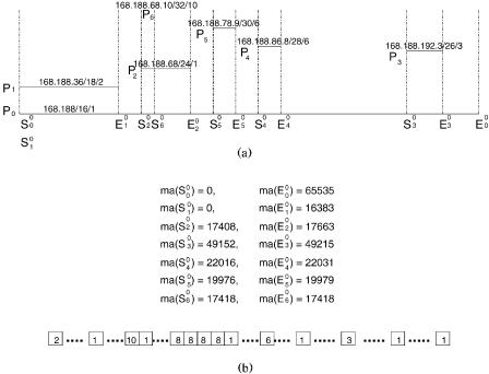
interval wmaŽSi0 ., maŽ Ei0 .x, and the set P of prefixes as a set of intervals. If all the intervals do not overlap, then the NHA can be directly constructed by setting NHA j s hi , maŽSi0 . F j F maŽ Ei0 .. However, in most cases, this may not be true. An overlap represents that a destination IP address has more than one matching address. However, the proposed design looks for the longest matching. Thus, if a memory address j belongs to a set P of intervals simultaneously, then we should set NHA j s hi , where pi is the longest prefix of P . For example, assume each route prefix is presented as prefixrprefix lengthrnext hop Žoutput port.. Then the set P of seven sorted prefixes given by 168.188r16r1, 168.188.36r18r2, 168.188.68r24r1, 1 6 8 .1 8 8 .1 9 2 .3 r 2 6 r 3 , 1 6 8 .1 8 8 .8 6 .8 r 2 8 r 6 , 1 6 8 .1 8 8 .7 8 .9 r 3 0 r 8 , 168.188.68.10r32r10 can be presented as the six intervals shown in Figure 13.26Ža.. The corresponding constructed NHA is given in Figure 13.26Žb..
Now, let us consider another example where we have three prefixes on a segment: p0 s 11.7r16r1, p1 s 11.7.12.10r32r2. Since the longest prefix is of length 32, the offset length k equals to 32 y 16 s 16 Žrecorded as 1111 in the offset length field.. Then the NHA for prefix 11.7 has 216 s 64K entries.
In this case, we have maŽS00 . s 0000000000000000 s 0, maŽ E00 . s 1111111111111111 s 65535, maŽS10 . s maŽ E10 . s 0000110000001010 s 3082.
Thus, we have NHA0 NHA3081 s 1, NHA3082 s 2, and NHA3083 NHA65535 s 1. For destination IP address 11.7.12.10, the offset is 3082, and the output
port can be found in NHA3082 s 2. For the destination IP address 11.7. x. y, 0 F x, y F 255, except 11.7.12.10, the offset q is 256 x q y, and the output
port can be found in NHA q s 1.
392 IP ROUTE LOOKUPS
Fig. 13.26 NHA construction example: Ža. interval presentation of P, Žb. constructed NHA.
The formal algorithm for constructing the NHA of a segment is given as follows.
NHA Construction Algorithm |
|
|
|
Input: The set of route prefixes of a segment. |
|
||
Output: The corresponding NHA of this segment. |
|
||
Step 1. Let li and hi be the length and output port of a route prefix pi , |
|||
respectively. |
|
|
|
Step 2. Let P s p0 , p1, . . . , pmy1 4 |
be the |
set of sorted prefixes of a |
|
segment. Thus, for any pair of prefixes pi |
and |
pj, i j if and only if |
|
li F lj. |
|
|
|
Step 3. Let k s lmy1 y 16 r* The size of NHA is 2 k *r |
|||
Step 4. For each prefix p in P, calculate S0 |
and |
E0. |
|
i |
i |
|
i |
Step 5.
For i s 0 to m y 1 do
NHA j s hi , maŽSi0 . F j F maŽ Ei0 .;
Step 6. Stop.
IP ROUTE LOOKUPS FOR GIGABIT SWITCH ROUTERS |
393 |
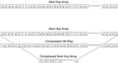
Fig. 13.27 NHA compression example.
In the worst case, the number of memory accesses for an IP address lookup is still two for this design, but the total amount of memory required is reduced significantly.
The forwarding database structure ŽNHAs. shown in Figure 13.25 can be further improved by employing the concept of compression. Thus, for each segment with offset length k 3, the associated NHA can be replaced by a codeword array ŽCWA. and a compressed NHA ŽCNHA.. To construct the CWA, we employ a compression bit map ŽCBM., one bit for each entry in the
original NHA. The compression rule is as follows. Let ai denote the value |
|
Žport number. of the ith entry of the NHA, bi the corresponding bit in the |
|
CBM, and cj the value Žport number. of the jth entry of the CNHA. Initially, |
|
c0 s a0 , b0 s 1, and j s 1. Then scan |
the NHA from left to right. If |
aiq1 s ai , then biq1 s 0, else biq1 s 1, cj |
s aiq1 , and j s j q 1. For exam- |
ple, the NHA shown in Figure 13.27Ža. can be compressed into the corre-
sponding CBM and CNHA as shown in Figure 13.27Žb..
The CBM and CNHA of a segment can be constructed directly without constructing the NHA first. The algorithm to construct the CBM and CNHA directly from the given prefixes of a segment is depicted as follows. Before starting, we need to note that for any two distinct prefixes in a segment, either one is completely contained in the other, or the two distinct prefixes have no entries overlapping with each other w5x.
Algorithm for CBM and CNHA Construction
Input: The set P s p0 , p1, . . . , pmy1 4 of sorted route prefixes of a segment and L s S00, E00, S10, E10, . . . , Sm0 y1 , Em0 y1 .
Output: CBM and CNHA.
Step 1. Sort L by memory address in the segment. For identical memory addresses, keep their order the same in L.
394 IP ROUTE LOOKUPS
Step 2 Let A s and stack C s .
Step 3.
Process the elements in L from left to right, and for each element do Begin
If the selected element is a start point Si0 then Push Si0 in C. Append Si0 to A.
Else r* It is an end point Ei0 *r Begin
Remove top element from stack C. If the top of stack C is Sjk then
Begin
Append Sjkq1 in A,
where opŽSjkq1 . s opŽSjk . and maŽSjkq1 . s maŽ Ei0 . q 1. Replace the top of stack C by Sjkq1.
End
Else r* Stack C is *r Do nothing.
End End
Step 4. Compact A: for consecutive elements Sjk and Spq, remove Sjk from A if maŽSjk . s maŽSpq ., and remove Spq from A if opŽSjk . s opŽSpq ..
Step 5. Remove each element Sjk from A whose maŽSjk . maŽ E00 ..
Step 6.
For i s 0 to A y1 do
r* A is the number of elements in A *r Begin
Let Sjk be the ith element in A; CBM p s 1, where p s maŽSjk .; CNHA i s opŽSjk .
End
Step 7. Stop.
The time complexity of the proposed algorithm is OŽn log n., where n is the number of prefixes in a segment. Since this algorithm constructs the CBM s and CNHA s directly from the given prefixes, the forwarding table can be built in a very short time.
The CBM should be encoded as a sequence of codewords ŽCWA. as follows. Each codeword consists of a map Ž16-bit. and a base Ž16-bit.. The
IP ROUTE LOOKUPS FOR GIGABIT SWITCH ROUTERS |
395 |
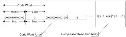
Fig. 13.28 Codeword array example.
CBM is treated as a bit stream and partitioned into a sequence of 16-bit maps. Then these maps are put into the codewords, one for each codeword, sequentially. The base of each codeword equals the number of 1’s accumulated in the maps of previous codewords. For example, the CBM shown in Figure 13.27Žb. is encoded as the codewords depicted in Figure 13.28. The maps of the first two codewords are 1000000010000000 and 0000000010001000, respectively. For the first codeword, the base has a value of zero. For the second codeword, since the number of 1’s accumulated in the maps of previous codewords is two, we have a base value of two. The base is used to indicate the start entry of the associated CNHA. Thus, for an offset value q, the output port can be computed as follows. Let cws s maps q bases be the code word contains this offset, where s s q div 16, with div referring to integer division. Let w s q mod 16 denote the corresponding bit of q in maps , and w stand for the number of accumulated 1’s from the 0th bit to the wth bit of maps. Then the output port of an offset value q is calculated as
opq s CHNA t , where t s bases q w y 1.
For example, consider the case shown in Figures 13.27 and 13.28 again.
For offset q s 8, we have s s 0, w s 8, and w s 2; then t s base0 q w
y 1 s 0 q 2 y 1 s 1, and the corresponding output port is CNHA1 s port 8. For offset value q s 25, we have s s 1, w s 9, and w s 1; then t s Žbase1 q w y1. s 2 q 1 y 1 s 2, and the corresponding output port is
CNHA2 s port 7.
To update the forwarding table, we can either rebuild a new one in a short time or use a special hardware design, such as dual-port memory or dualmemory banks.
13.8.2Performance
The proposed route lookup mechanism needs only tiny SRAM and can be easily implemented in hardware. Based on the data obtained from w11x, a large routing table with 40,000 routing entries can be compacted to a
396 IP ROUTE LOOKUPS
forwarding table of 450 470 Kbyte. Most of the address lookups can be done by a memory access. In the worst case, the number of memory accesses for a lookup is three. When implemented in a pipeline in hardware, the proposed mechanism can achieve one routing lookup every memory access. With current 10-ns SRAM, this mechanism furnishes approximately 100 106 routing lookups per second.
13.9IP ROUTE LOOKUPS USING TWO-TRIE STRUCTURE
IP route lookups based on a so-called two-trie structure are described here. In the two-trie structure, the nodes representing the front and rear parts of the prefixes are shared so that the resulting number of nodes in the structure can be reduced. Moreover, it still provides fast lookups. The original two-trie structure was proposed by Aoe et al. w1x. Their algorithms can be adapted to various applications as long as searching is done in the exact match manner. A new version of the two-trie structure and its related algorithms that was specifically designed for doing IP route lookups was described in w7x. Specifically, the lookup algorithm does the longest-prefix match, while the updating algorithms have the property in maintaining the next hop information of the longest prefixes in the structure when the prefix addition or deletion is performed.
A K-bit two-trie structure consists of two K-bit tries, the front trie and the rear trie, joining leaf nodes together in the middle. A node is called a front Žrear. node if it is on the front Žrear. trie. Both tries are allowed to traverse in both directions. The direction outgoing from the root node of each trie to its own children nodes is called the forward direction, while the opposite one is called the backward direction.
We assume that any route prefix Žor IP address. X of length Y bits is represented in the dotted decimal form ² xŽ0.. xŽ1.. . . . . xŽ N .:, where xŽi. is a K-bit-wide integer of the prefix X, 0 F i F N y 1; xŽ N . is a special symbol; and N s wYrK . For example, given K s 8, a prefix X s 128.238.0.0 of length Y s 16 bits would be represented as ²128.238. :. The special symbolindicates the end of the prefix and is used to distinguish, for example, between ²128.238. : and ²128.238.3. :, so that a prefix is not allowed within another prefix. If Y is not a multiple of K bits Žfor example, if K s 8, X s 128.238.32.0, and Y s 20., then X will be transformed to a set of prefixes ²128.238. j. :, where 32 F j F 47.
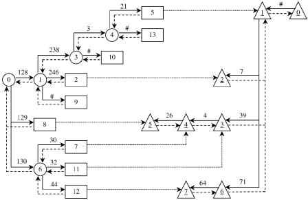
Figure 13.29 shows an example of the two-trie structure when K s 8. The nodes of both tries are represented by the node numbers, where each root node is represented by the node number 0. Since we use the same node numbers on both tries, the node numbers of the rear trie are distinguished by an underline. The forward direction is represented by a solid line, and the backward one by a dashed line. Each leaf node on the front trie Žthe last node on the front trie in each path when traversing the front trie in the forward direction. is called a separate node. Note that the separate nodes are
IP ROUTE LOOKUPS USING TWO-TRIE STRUCTURE |
397 |
Fig. 13.29 An example of the two-trie structure when K s 8. Ž 1999 IEEE..
the nodes that differentiate a prefix from other prefixes. The next hop of each prefix is stored at each separate node. In Figure 13.29, separate nodes Žnodes 2, 5, 7, 8, 9,10, 11, 12, 13. are represented by using rectangles, while other front nodes Žnodes 0, 1, 3, 4, 6. are represented by using circles. Rear nodes Žnodes 0, 1, 2, 3, 4, 5, 6, 7. are represented by using triangles.
13.9.1IP Route Lookup Algorithm
In this subsection, we will illustrate how to do IP lookups. The IPLookup Ž X . algorithm is shown below. The input of the function is the IP destination address X of an incoming packet, which is in the dotted decimal form. The function returns the next hop of the longest matching prefix found in the two-trie structure.
Algorithm IPLookup ( X )
1.Let Z be the variable that stores the next hop of the longest matching prefix. Initially Z is the default next hop.
2.Start to do an IP lookup from the root node of the front trie by matching each K-bit part of the destination address X of the packet with prefixes in the two-trie structure.
3.If there is a match, the traversal is moved to the child node at the next level of the front trie.
398IP ROUTE LOOKUPS
4.Whenever a new front node is arrived at, the algorithm first looks for its child node corresponding to the symbol Žwhich must be the separate node.. If the node is found, it means that the two-trie structure contains a longer matching prefix, so the variable Z is updated with the next hop value of this prefix retrieved from the separate node.
5.When the separate node is reached, matching continues to the rear trie by using a pointer at the separate node Žshown as a dashed line in Fig. 13.29.. Matching on the rear trie is done in the backward direction.
6.The algorithm stops whenever
Ža. a mismatch is detected somewhere in the structure Žin such a case, the current value of Z is returned as the next hop., or
Žb. the traversal reaches the root node of the rear trie Žno mismatch is detected.. This means that the destination address X of the packet is actually stored as a prefix in the structure. The variable Z is updated with the next hop value of the prefix stored at the separate node we previously visited and returned as the output of the function.
Suppose that we would like to look up the destination address X s ²130.44.64.71. : from the two-trie structure shown in Figure 13.29. The lookup starts from the root node of the front trie and proceeds along the front trie by moving to the next nodes 6 and 12. Then, the traversal is transferred to the rear trie and continues through the rear nodes 7, 6, and 1 until the root node of the rear trie is reached. The algorithm stops, and the next hop stored at the separate node 12 is assigned to the variable Z and returned as the output. Note that the algorithm can be improved by keeping track of the number of parts of the address X it has already matched. Instead of traversing until reaching the root node of the rear trie, in this example the algorithm can stop when 71, which is the last part of X, is matched at the rear node 6.
Now let us change the destination address X to ²130.44.64.72. : and do the lookup again. When the traversal is at the rear node 6, there is no match with 72. The algorithm stops and returns the current value Z, which is the default next hop, as the output.
13.9.2Prefix Update Algorithms
In this subsection, we will introduce the AddPrefixŽ X, Y, Z. and DelPrefixŽ X, Y . algorithms, which perform the addition and deletion of a prefix X of length Y bits with the next hop Z. Note that when Y is not a multiple of K bits, the prefix X is first transformed to a set of the new
IP ROUTE LOOKUPS USING TWO-TRIE STRUCTURE |
399 |
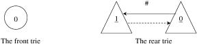
Fig. 13.30 Initialization of the front and rear tries before adding route prefix.
prefixes and then the addition and deletion are performed for each prefix that has just been generated.
Before we start to build up a routing table by adding a prefix, initially the front trie has only the root node, the node 0, while the rear trie has two nodes, 0 and 1, and pointers corresponding to the symbol , as shown in Figure 13.30.
Algorithm AddPrefix( X, Y, Z)
1.Start by traversing nodes from the root node of the front trie to the root node of the rear trie to check whether the prefix X is in the structure.
2.If the prefix X is in the structure, the traversal will finally reach the root node of the rear trie. The algorithm retrieves the current length of X from the separate node we just visited along the path and compares it with the length Y. If Y is greater than or equal to the current length of X, the algorithm will update the length and the next hop of X, which are stored at the separate node along the path we just visited, with the values Y and Z, respectively. Then the algorithm stops.
3.If the prefix X is a new one, a mismatch is detected somewhere in the structure. There are two possible cases:
Ža. The mismatch is detected on the front trie.
i.Create a new separate node for matching the K-bit part of the prefix X that starts to be different from any other prefixes in the two-trie structure. Store the length Y and the next hop Z at this node.
ii.Adding the remaining K-bit parts of the prefix X to the rear trie. Since the remaining parts of X can be shared with those of other prefixes in the structure, the algorithm traverses the rear trie from the root node in the forward direction and matches the remaining parts of X from the end. Some new rear nodes may be created for the parts of X that have no matches.
iii.Set a linkage to connect the separate node in step 3Ža.i with the rear trie in step 3Ža.ii.