

Broadband Packet Switching Technologies
.pdf380 IP ROUTE LOOKUPS
Fig. 13.14 Example of two tables containing three routes.
Consider the following examples of how route lookups are performed on the table in Figure 13.14. Assume that the following routes are already in the table: 10.54r16, 10.54.34r24, 10.54.34.192r26. The first route requires entries in TBL24 that correspond to the 24-bit prefixes 10.54.0 through 10.54.255 Žexcept for 10.54.34.. The second and third routes require that the second table be used Žbecause both of them have the same first 24 bits and one of them is more than 24 bits long.. So, in TBL24, we insert a one followed by an index Žin the example, the index equals 123. into the entry corresponding to the prefix 10.54.34. In the second table, we allocate 256 entries starting with memory location 123 256. Most of these locations are filled in with the next hop corresponding to the 10.54.34 route, but 64 of them wthose from Ž123 256. q 192 to Ž123 256. q 255x are filled in with the next hop corresponding to the 10.54.34.192 route.
Now assume that a packet arrives with the destination address 10.54.22.147. The first 24 bits are used as an index into TBL24, and will return an entry with the correct next hop Ž A.. If a second packet arrives with the destination address 10.54.34.23, the first 24 bits are used as an index into the first table, which indicates that the second table must be consulted. The lower 15 bits of the entry Ž123 in this example. are combined with the lower 8 bits of the destination address, and used as an index into the second table. After two memory accesses, the table returns the next hop Ž B.. Finally, let’s assume that a packet arrives with the destination address 10.54.34.194. Again, TBL24 indicates that TBLlong must be consulted, and the lower 15 bits of the entry
IP LOOKUPS USING MULTIWAY SEARCH |
381 |
are combined with the lower 8 bits of the address to form an index into the second table. This time the index an entry associated with the 10.54.34.192r26 prefix ŽC..
13.6.2Performance
As a summary, the advantages and disadvantages associated with the basic DIR-24-8-BASIC scheme are listed:
Advantages:
1.Although Žin general. two memory accesses are required, these accesses are in separate memories, allowing the scheme to be pipelined.
2.Except for the limit on the number of distinct 24-bit-prefixed routes with length greater than 24 bits, this infrastructure will support an unlimited number of routes.
3.The total cost of memory in this scheme is the cost of 33 Mbyte of DRAM. No exotic memory architectures are required.
4.The design is well suited to hardware implementation.
5.When pipelined, 20 106 packets per second can be processed with currently available 50-ns DRAM. The lookup time is equal to one memory access time.
Disadvantages:
1.Memory is used inefficiently.
2.Insertion and deletion of routes from the table may require many memory accesses.
13.7IP LOOKUPS USING MULTIWAY SEARCH
Lampson et al. w9x showed how to apply a binary search to find best-matching prefixes using two routing entries per prefix and doing some precomputations. They also proposed the way to use an initial array indexed by the first X bits of the address together with taking advantage of cache line size to do a multiway search with six-way branching. Measurements using a practical routing table of 30,000 entries yield a worst case lookup time of 490 ns, five times faster than the Patricia trie scheme.
13.7.1Adapting Binary Search for Best-Matching Prefix
Binary search can be used to solve the best-matching-prefix problem, but only after several subtle modifications. Assume for simplicity, in the examples, that we have 6-bit addresses and three prefixes 1*, 101*, and 10101*.
382 IP ROUTE LOOKUPS
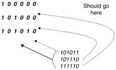
Fig. 13.15 Placing the three prefixes 1*, 101*, and 10101* in a binary search table by padding each prefix with 0’s to make 6-bit strings and sorting the resulting strings. Note that the addresses 101011, 101110, and 111110 all end up in the same region in the table.
First, binary search does not work with variable-length strings. Thus the simplest approach is to pad each prefix to be a 6-bit string by adding zeros. This is shown in Figure 13.15.
Now consider a search for the three 6-bit addresses 101011, 101110,and 111110. Since none of these addresses are in the table, binary search will fail. Unfortunately, on failure all three of these addresses will end up at the end of the table, because all of them are greater than 101010, which is the last element in the table. Notice however that each of these three addresses Žsee Fig. 13.15. has a different best-matching prefix.
Thus we have two problems with naive binary search: first, when we search for an address, we end up far away from the matching prefix Žpotentially requiring a linear search.; second, multiple addresses that match to different prefixes end up in the same region in the binary table ŽFig. 13.15..
To solve the second problem, we recognize that a prefix like 1* is really a range of addresses from 100000 to 111111. Thus instead ofen coding 1* by just 100000 Žthe start of the range., we encode it using both start and end of range. Thus, each prefix is encoded by two full-length bit strings. These bit strings are then sorted. The result for the same three prefixes is shown in Figure 13.16. The start and end of a range Žcorresponding to a prefix. are connected by a line in Figure 13.16. Notice how the ranges are nested. If we now try to search for the same set of addresses, they each end in a different region in the table. To be more precise, the search for address 101011 ends in an exact match. The search for address 101110 ends in a failure in the region between 101011 and 101111 ŽFig. 13.16., and the search for address 111110 ends in a failure in the region between 101111 and 111111. Thus it appears that the second problem Žmultiple addresses that match different prefixes ending in the same region of the table. has disappeared.
To see that this is a general phenomenon, consider Figure 13.17. The figure shows an arbitrary binary search table after every prefix has been
IP LOOKUPS USING MULTIWAY SEARCH |
383 |
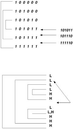
Fig. 13.16 Each prefix is encoded in the table as a range using two values: the start and end of range. This time the addresses that match different prefixes end up in different ranges.
Fig. 13.17 Why each range in the modified binary search table maps to a unique prefix.
encoded by the low points Žmarked L in Fig. 13.17. and the high points Žmarked H . of the corresponding range. Consider an arbitrary position indicated by the solid arrow. If binary search for address A ends up at this point, which prefix should we map A to? It is easy to see the answer visually from Figure 13.17. If we start from the point shown by the solid arrow and we go back up the table, the prefix corresponding to A is the first L that is not followed by a corresponding H Žsee dashed arrow in Fig. 13.17..
Why does this work? Since we did not encounter an Hcorresponding to this L, it clearly means that A is contained in the range corresponding to this prefix. Since this is the first such L, that the smallest such range. Essentially, this works because the best matching prefix has been translated to the problem of finding the narrowest enclosing range.
Unfortunately, the solution depicted in Figure 13.16 and Figure 13.17 does not solve the first problem: notice that binary search ends in a position that is
384 IP ROUTE LOOKUPS
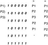
Figure 13.18 The final modified binary search table with precomputed prefixes.
far away Žpotentially. from the actual prefix. If we were to search for the prefix Žas described earlier., we could have a linear-time search. However, the modified binary search table shown in Figure 13.17 has a nice property we can exploit: Any region in the binary search between two consecuti®e numbers corresponds to a unique prefix. As described earlier, the prefix corresponds to the first L before this region that is not matched by a corresponding H that also occurs before this region. Similarly, every exact match corresponds to a unique prefix.
But if this is the case, we can precompute the prefix corresponding to each region and to each exact match. This can slow down insertion. However, the insertion or deletion of a new prefix should be a rare event Žthe next hop to reach a prefix may change rapidly, but the addition of a new prefix should be rare. compared to packet forwarding times. Thus slowing down insertion costs for the sake of faster forwarding is a good idea. Essentially, the idea is to add the dashed line pointer shown in Figure 13.17 to every region.
The final table corresponding to Figure 3.17 is shown in Figure 13.18. Notice that with each table entry E, there are two precomputed prefix values. If binary search for address A ends in a failure at E, it is because A E. In that case, we use the pointer corresponding to E. On the other hand, if binary search for address A ends in a match at E, we use the s pointer. Notice that for an entry like 101011, the two entries are different. If address A ends up at this point and is greater than 101011, clearly the right prefix is P2 s 101*. On the other hand, if binary search for address A ends up at this point with equality, the right prefix is P3 s 10101*. Intuitively, if an address A ends up equal to the high point of a range R, then A falls within the range R; if A ends up greater than the high point of R, then A falls within the smallest range that encloses R.
13.7.2Precomputed 16-Bit Prefix Table
The worst case number of memory accesses of the basic binary search scheme can be improved with a precomputed table of best-matching prefixes for the first Y bits. The main idea is to effectively partition the single binary search
IP LOOKUPS USING MULTIWAY SEARCH |
385 |
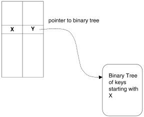
Fig. 13.19 The array element with index X will have the best-matching prefix of X Žsay Y . and a pointer to a binary tree of all prefixes that have X as a prefix.
table into multiple binary search tables for each value of the first Y bits. This is illustrated in Figure 13.19. Y s 16 is chosen for what follows, as the resulting table size is about as large as we can afford, while providing maximum partitioning.
The best-matching prefixes for the first 16-bit prefixes can be precomputed and stored in a table. This table would then have Max s 65536 elements. For each index X of the array, the corresponding array element stores the best matching prefix of X. Additionally, if there are prefixes of longer length with that prefix X, the array element stores a pointer to a binary search table or tree that contains all such prefixes.
Without the initial table, the worst case possible number of memory accesses is log2 N q 1, where N is the number of prefixes in the table. For large databases this could be 16 or more memory accesses. For a publicly available IP backbone router database w11x, this simple trick of using an array as a front end reduces the maximum number of prefixes in each partitioned table to 336 from the maximum value of over 30,000. This leads to a worst case of 10 memory accesses.
13.7.3Multiway Binary Search: Exploiting the Cache Line
Today processors have wide cache lines. The Intel Pentium Pro has a cache line size of 32 bytes. Main memory is usually arranged in a matrix form, with rows and columns. Accessing data given a random row address and column address has an access time of 50 to 60 ns. However, when using SDRAM, filling a cache line of 32 bytes, which is a burst access to four contiguous
386 IP ROUTE LOOKUPS
64-bit DRAM locations, is much faster than accessing four random DRAM locations. When accessing a burst of contiguous columns in the same row, while the first datum would be available only after 60 ns, further columns would be available much faster.
By taking the advantage of this observation, data structures can be reorganized to improve locality of access. To make use of the cache line fill and the burst mode, keys and pointers in search tables can be laid out to allow multiway search instead of binary search. This effectively allows us to reduce the search time of binary search from log2 N to log kq1 N, where k is the number of keys in a search node. The main idea is to make k as large as possible so that a single search node Žcontaining k keys and 2 k q 1 pointers. fits into a single cache line. If this can be arranged, an access to the first word in the search node will result in the entire node being prefetched into cache. Thus the accesses to the remaining keys in the search node are much cheaper than a memory access.
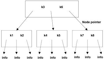
If we use k keys per node, then we need 2 k q 1 pointers, each of which is a 16-bit quantity. Based on a Pentium Pro processor Žwith the cache line size of 32 bytes., we can choose k s 5 keys and do a six-way search. For example, if there are keys k1, . . . , k8 , a three-way tree is given in Figure 13.20. The initial full array of 16 bits followed by the six-way search is depicted in Figure 13.21.
From a practical routing table obtained from Merit w11x containing 30,000 routing entries, it is found that after using a16-bit initial array, the worst case has 336 routing entries left for doing a six-way search. This leads to a worst case of four memory accesses, since 64 s 1296 takes only four memory accesses.
Each node in the six-way search table has five keys k1 to k5, each of which is 16 bits. There are equal to pointers p1 to p5 corresponding to each of these keys. Pointers p01 to p56 correspond to ranges demarcated by the keys. This is shown in Figure 13.22. Among the keys we have the relation
Fig. 13.20 A three-way tree for eight keys.

IP LOOKUPS USING MULTIWAY SEARCH |
387 |
Fig. 13.21 The initial 16-bit array, with pointer to the corresponding six-way search nodes.
Fig. 13.22 The structure of the six-way search node.
ki F kiq1 . Each pointer has a bit that says it is an information pointer or a next-node pointer.
IP Route Lookup Algorithm:
1.Index into the first 16-bit array, using the first 16 bits of the address.
2.If the pointer at the location is an information pointer, return it. Otherwise enter the six-way search with the initial node given by the pointer, the key being the next 16 bits of the address.
388IP ROUTE LOOKUPS
3.In the current six-way node, locate the key. We use binary search
among the keys within a node. If the key equals any of the keys keyi in the node, use the corresponding pointer ptri. If the key falls in any range formed by the keys, use the pointer ptri, iq1 . If this pointer is an information pointer, return it; otherwise repeat this step with the new six-way node given by the pointer.
13.7.4Performance
For a practical routing table, a basic binary search scheme for the bestmatching prefix requires 16 memory accesses for an IP route lookup. By using an initial precomputed 16-bit array, the number of required memory accesses can be reduced to 9.
By applying a six-way branching search technique Žafter using a 16-bit initial array. that exploits the fact that a Pentium Pro processor prefetches a 32-byte cache line when doing a memory access, we obtain a worst case of five memory accesses . By using a Pentium Pro machine with a 200-MHz clock and a sample of a practical routing table with over 32,000 route entries, a worst case time of 490 ns and an average time of 100 ns for an IP route lookup are obtained. The structure uses 0.7 Mbyte of memory.
13.8IP ROUTE LOOKUPS FOR GIGABIT SWITCH ROUTERS
Huang et al. w6x proposed a route-lookup mechanism that needs only tiny SRAM and can be implemented using a hardware pipeline. The forwarding table, based on their scheme, is small enough to fit into a faster SRAM with low cost. For example, a large routing table with 40,000 routing entries can be compacted into a forwarding table of 450 470 kbytes costing less than US$30. Most route lookups need only one memory access; no lookup needs more than three memory accesses.
13.8.1Lookup Algorithms and Data Structure Construction
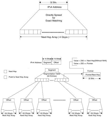
The most straightforward way to implement a lookup scheme is to have a forwarding table in which an entry is designed for each 32-bit IP address, as depicted in Figure 13.23. This design needs only one memory access for each IP-route lookup, but the size of the forwarding table wnext-hop array ŽNHA.x is huge Ž232 bytes s 4 Gbyte. w5x.
To reduce the size of the forwarding table, an indirect lookup can be employed Žsee Fig. 13.24. w5x. Each IP address is split into two parts: Ža. segment Ž16-bit. and Žb. offset Ž16-bit.. The segmentation table has 64K entries Ž216 ., and each entry Ž32-bit. records either the next hop Žport number, value 256. of the routing or a pointer Žvalue 255. that points
IP ROUTE LOOKUPS FOR GIGABIT SWITCH ROUTERS |
389 |
Fig. 13.23 Direct lookup mechanism.
Fig. 13.24 Indirect lookup mechanism.
to the associated NHA. Each NHA consists of 64K entries Ž216 . and each entry Ž8-bit. records the next hop Žport number. of the destination IP address. Thus, for a destination IP address a.b. x. y, the a.b is used as the index of the segmentation table and the x. y is employed as the index of the associated NHA, if necessary. Thus, for a segment a.b, if the length of the longest prefix belonging to this segment is less than or equal to 16, then the corresponding entries of the segmentation table store the output port directly, and the associated NHA is not necessary. On the other hand, if the length of the longest prefix belonging to this segment is greater than 16, then an associated 64-Kbyte NHA is required. In this design, a maximum of two