

Broadband Packet Switching Technologies
.pdf370 IP ROUTE LOOKUPS
Fig. 13.5 A 1-bit trie structure for IP route lookups.
An example is shown in Figure 13.5. Each node has a flag associated with it, which indicates whether the particular route prefix terminated there is in the routing table. The flag is indicated with an asterisk. Assume that the destination address 10101101 is given. The IP lookup starts at the top and traverses the path indicated by the destination address, remembering the last time a flag Žan asterisk. was seen. Starting at the top, the zero-length prefix has a flag. The first bit of 10101101 is 1, so we go to the right and get to the node with the name 1. There is no asterisk, so 4 is still the longest prefix matched so far. The second and third bits of 10101101 are 0 and 1, so we go to the left and right to the node 101*. Here an asterisk is found, so the longest matching prefix is updated from 4 to 101. The next bit is 0. We go to the node 10101. The next bit is 1, but there is no pointer marked 1 out of the node 1010. Thus, the lookup is stopped here, and the longest matching prefix is 101.
Maintaining the trie structure is not difficult. To add a route prefix, say 1011, simply follow the pointers to where 1011 would be in the tree. If no pointers exist for that prefix, they should be added. If the node for the prefix already exists, it needs to be marked as being in the forwarding table, that is, an asterisk must be added. To delete a route prefix that has no children, the node and the pointer pointing to it are deleted and the parent node is examined. If it has another child or is marked with an asterisk, it is left alone. Otherwise, that node is also deleted and its parent node is examined. The deletion process is repeated up the tree until a node that has another child or is marked is found.
Using the 1-bit trie structure for the IP route lookups has the drawback in that the number of memory accesses in the worst case could be 32 for IPv4.
The performance of lookups can be substantially improved by using a multibit trie structure. This more general idea was suggested by Srinivasan and Varghese w14x. In the multibit, say K-bit, trie structure, each node contains 2 K pointers. Each route prefix in the forwarding table is expanded to include new prefixes whose lengths are the smallest numbers that are greater than or equal to the original length and also multiples of K bits. For
IP ROUTE LOOKUP BASED ON STANDARD TRIE STRUCTURE |
371 |
TABLE 13.1 An Example of Expanding the Route
Prefixes by Using 2-Bit Trie Structure
Forwarding Table |
|
Original |
Expanded |
|
|
P1 s 0* |
01* ŽP1. |
P2 s 1* |
00* ŽP1. |
P3 s 10* |
10* ŽP3. |
P4 s 111* |
11* ŽP2. |
P5 s 1000* |
1110* ŽP4. |
P6 s 11001* |
1111* ŽP4. |
|
1000* ŽP5. |
|
110010* ŽP6. |
|
110011* ŽP6. |
|
|
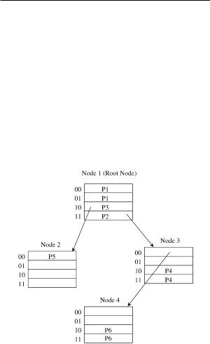
Fig. 13.6 The 2-bit trie structure corresponding to the forwarding table in Table 13.1.
example, a routing table, shown in the left column of Table 13.1, contains route prefixes P1 P6. The asterisk in each route prefix indicates that the remaining bits are insignificant. By using a 2-bit trie structure, the expanded version of the forwarding table can be obtained as shown in the right column of Table 13.1. Note that the prefix P2 s 1* can be expanded into 10* and 11*, but 10* is not used, since it overlaps P3, which is the longer matching prefix. The corresponding 2-bit trie structure is also shown in Figure 13.6.
The traversal to the node at each level of the K-bit trie is based on each K-bit part of the destination address of the packet. The advantage of the
372 IP ROUTE LOOKUPS
K-bit trie structure is that it provides fast lookups; its disadvantage is the large memory space that is required for nodes of the structure.
13.4PATRICIA TREE
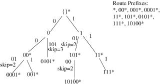
Traditional implementations of routing tables use a version of Patricia trees w10x. A Patricia tree is an improvement on the 1-bit trie structure. It is based on the observation that each internal node of the trie that does not contain a route prefix and has only one child can be removed in order to shorten the path from the root node. By removing some internal nodes, the technique requires a mechanism to record which nodes are missing. A simple mechanism is to store a number, the skip ®alue, in each node that indicates how many bits have been skipped on the path. The path-compressed version of the 1-bit trie in Figure 13.5 is shown in Figure 13.7.
Suppose that the destination address 10001101 is given. The IP lookup starts at the top and traverses the path indicated by the destination address, remembering the last time a flag Žan asterisk. was seen. Starting at the top, the zero-length prefix has a flag. The first bit of 10001101 is 1, so we go to the right and get to the node with the name 1. There is no asterisk at this node, so 4 is still the longest prefix matched so far. Since the second bit of 10101101 is 0, we go to the left. At the left branch, the skip value 2 indicates that in order to take the 0 branch out of the node 1, we must match the two subsequent bits 01. Since the second and the third bits of 10001101 are 00, there is no match. Thus, 4 is returned as the longest matching prefix.
With around 40,000 prefix entries in a routing table, a straightforward implementation of Patricia tree structure is almost 2 Mbyte, and 15 or 16 nodes must be traversed to find a routing entry. There are optimizations that can reduce the size of a Patricia tree and improve lookup speeds. Nevertheless, the data structure is large, and too many expensive memory accesses are needed to search it.
Fig. 13.7 The Patricia tree corresponding to the 1-bit trie in Figure 13.5.
SMALL FORWARDING TABLES FOR FAST ROUTE LOOKUPS |
373 |
13.5 SMALL FORWARDING TABLES FOR FAST ROUTE LOOKUPS
Degermark et al. w2x proposed a data structure that can represent large routing tables in a very compact form, small enough to fit entirely in a cache. This provides an advantage in that the fast IP route-lookup algorithm can be implemented in software running on general-purpose microprocessors.
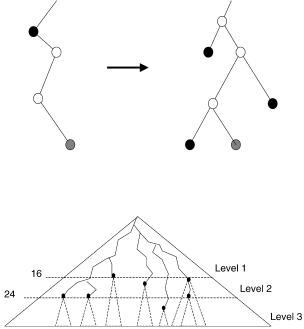
The forwarding table is a representation of the binary tree spanned by all routing entries. This is called the prefix tree. The prefix tree is required to be full, that is, such that each node in the tree has either two or no children. Nodes with a single child must be expanded to have two children; the children added in this way are always leaves, and their next-hop information will be the same as that of the closest ancestor with next-hop information.
This procedure, illustrated in Figure 13.8, increases the number of nodes in the prefix tree, but allows building a small forwarding table. Note that it is not needed to actually build the prefix tree to build the forwarding table. The prefix tree is used to simplify the explanation. The forwarding table can be built during a single pass over all routing entries.
The forwarding table is essentially a tree with three levels. As shown in Figure 13.9, level 1 of the data structure covers the prefix tree down to depth 16, level 2 covers depths 17 to 24, and level 3 depths 25 to 32. Wherever a
Fig. 13.8 Expanding the prefix tree to be complete.
Fig. 13.9 The three levels of the data structure.
374 IP ROUTE LOOKUPS
part of the prefix tree extends below level 16, a level-2 chunk describes that part of the tree. Similarly, chunks at level 3 describe parts of the prefix tree that are deeper than 24. The result of searching a level of the data structure is either an index into the next-hop table or an index into an array of chunks for the next level.
13.5.1Level 1 of Data Structure
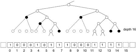
Imagine a cut through the prefix tree at depth 16. The cut is stored in a bit vector, with one bit per possible node at depth 16. For this, 216 bits s 64 Kbit s 8 Kbyte are required. To find the bit corresponding to the initial part of an IP address, the upper 16 bits of the address is used as an index into the bit vector.
When there is a node in the prefix tree at depth 16, the corresponding bit in the vector is set. Also, when the tree has a leaf at a depth less than 16, the lowest bit in the interval covered by that leaf is set. All other bits are zero. A bit in the bit vector can thus be
a one representing that the prefix tree continues below the cut: a root head Žbits 6, 12, and 13 in Fig. 13.10., or
a one representing a leaf at depth 16 or less: a genuine head Žbits 0, 4, 7, 8, 14, and 15 in Fig. 13.10., or
zero, which means that this value is a member of a range covered by a leaf at a depth less than 16 Žbits 1, 2, 3, 5, 9, 10, and 11 in Fig.13.10..
For genuine heads an index to the next-hop table is stored. Members will use the same index as the largest head smaller than the member. For root heads, an index to the level-2 chunk that represents the corresponding subtree is stored.
The head information is encoded in 16-bit pointers stored in an array. Two bits of the pointer encodes what kind of pointer it is, and the 14 remaining bits are indices either into the next-hop table or into an array containing level-2 chunks.
Fig. 13.10 Part of cut with corresponding bit vector.
SMALL FORWARDING TABLES FOR FAST ROUTE LOOKUPS |
375 |
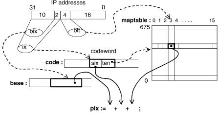
Fig. 13.11 Finding the pointer index.
So how to find the proper pointer? The bit vector is divided into bit masks of length 16, and there are 212 s 4096 of those. The position of a pointer in the array is obtained by adding three entities: a base index, a 6-bit offset, and a 4-bit offset. The base index plus 6-bit offset determines where the pointers corresponding to a particular bit mask are stored. The 4-bit offset specifies which pointer among those to retrieve. Figure 13.11 shows how these entities are found. The following paragraphs elaborate on the procedure.
Since bit masks are generated from a full prefix tree; not all combinations of the 16 bits are possible. A nonzero bit mask of length 2 n can be any combination of two bit masks of length n or the bit mask with value 1. Let aŽn. be the number of possible nonzero bit masks of length 2 n. Then aŽn. is given by the recurrence
aŽ0. s 1, aŽ n q 1. s 1 q aŽ n.2 .
The number of possible bit masks with length 16 is thus aŽ4. q 1 s 678; the additional one is because the bit mask can be zero. An index into a table with an entry for each bit mask thus only needs 10 bits.
A table, maptable, is kept to map bit numbers within a bit mask to 4-bit offsets. The offset specifies how many pointers to skip over to find the wanted one, so it is equal to the number of set bits smaller than the bit index. These offsets are the same for all forwarding tables, regardless of what values the pointers happen to have. maptable is constant; it is generated once and for all.
The actual bit masks are not needed, and instead of the bit vector an array of 16-bit codewords consisting of a 10-bit index into maptable plus a 6-bit offset is kept. A 6-bit offset covers up to 64 pointers, so one base index per four codewords is needed. There can be at most 64K pointers, so the base indices need to be at most 16 bits Ž216 s 64K..
376 IP ROUTE LOOKUPS
The following steps are required to search the first level of the data structure; the array of codewords is called code, and the array of base addresses is called base. Figure 13.11 illustrates the procedure.
ix := high 12 bits of IP address
bit := low 4 of high 16 bits of IP address
codeword := code[ix]
ten := ten bits from codeword six := six bits from codeword bix := high ten bits of IP address
pix := base[bix]+ six + maptable[ten][bit] pointer := level1_pointers[pix]
The code is extremely simple. A few bit extractions, array references, and additions are all that is needed. No multiplication or division instructions are required except for the implicit multiplications when indexing an array.
A total of seven bytes needs to be accessed to search the first level: a two-byte codeword, a two-byte base address, one byte Ž4 bits, really. in maptable, and finally a two-byte pointer. The size of the first level is 8 Kbyte for the code word array, plus 2 Kbyte for the array of base indices, plus a number of pointers. The 5.3 Kbytes required by maptable is shared among all three levels.
When the bit mask is zero or has a single bit set, the pointer must be an index into the next-hop table. Such pointers can be encoded directly into the codeword, and thus maptable need not contain entries for bit masks 1 and 0. The number of maptable entries is thus reduced to 676 Žindices 0 through 675.. When the ten bits in the codeword Žten above. are larger than 675, the codeword represents a direct index into the next-hop table. The six bits from the code word are used as the lowest six bits in the index, and ten676 gives the upper bits of the index. This encoding allows at most Ž1024 y 676. 26 s 22,272 next-hop indices, which is more than the 16 K we are designing for. This optimization eliminates three memory references when a routing entry is located at depth 12 or more, and reduces the number of pointers in the pointer array considerably. The cost is a comparison and a conditional branch.
13.5.2Levels 2 and 3 of Data Structure
Levels 2 and 3 of the data structure consist of chunks. A chunk covers a subtree of height 8 and can contain at most 28 s 256 heads. A root head is level n. There are three varieties of chunks, depending on how many heads the imaginary bit vector contains. When there are
1 8 heads, the chunk is sparse and is represented by an array of the 8-bit indices of the heads, plus eight 16-bit pointers: a total of 24 bytes.
ROUTE LOOKUPS IN HARDWARE AT MEMORY ACCESS SPEEDS |
377 |
9 64 heads, the chunk is dense. It is represented analogously to level 1, except for the number of base indices. The difference is that only one base index is needed for all 16 codewords, because 6-bit offsets can cover all 64 pointers. A total of 34 bytes are needed, plus 18 to 128 bytes for pointers.
65 256 heads, the chunk is ®ery dense. It is represented analogously to level 1. The 16 codewords and 4 base indices give a total of 40 bytes. In addition, the 65 to 256 pointers require 130 to 512 bytes.
Dense and very dense chunks are searched analogously to level 1. For sparse chunks, the first to eighth values are placed in decreasing order. To avoid a bad worst case when searching, the fourth value is examined to determine if the desired element is among the first four or last four elements. After that, a linear scan determines the index of the desired element, and the pointer with that index can be extracted. The first element less than or equal to the search key is the desired element. At most 7 bytes need to be accessed to search a sparse chunk.
Dense and very dense chunks are optimized analogously to level 1 as described in Section 13.5.1. In sparse chunks, two consecutive heads can be merged and represented by the smaller if their next hops are identical. When deciding whether a chunk is sparse or dense, this merging is taken into account, so that the chunk is deemed sparse when the number of merged heads is 8 or less. Many of the leaves that were added to make the tree full will occur in order and have identical next hops. Heads corresponding to such leaves will be merged in sparse chunks. This optimization shifts the chunk distribution from the larger dense chunks towards the smaller sparse chunks. For large tables, the size of the forwarding table is typically decreased by 5% to 15%.
13.5.3Performance
Forwarding tables are constructed from routing tables of various sizes. For the largest routing tables with 40,000 routing entries, the data structure is 150 160 Kbyte, which is small enough to fit in the cache of a conventional general-purpose processor. With the table in the cache, a 200-MHz Pentium Pro or a 333-MHz Alpha 21164 can perform a few million IP lookups per second without special hardware, and no traffic locality is assumed.
13.6 ROUTE LOOKUPS IN HARDWARE AT MEMORY ACCESS SPEEDS
Gupta et al. w5x proposed a route lookup mechanism that, when implemented in a pipelined fashion in hardware, can achieve one route lookup every memory access. It is called the DIR-24-8-BASIC scheme. With current 50-ns
378 IP ROUTE LOOKUPS
DRAM, this corresponds to approximately 20 106 packets per second, much faster than current commercially available routing lookup schemes.
The technique presented here is based on the following assumptions:
1.Memory is cheap.
2.The route lookup mechanism will be used in routers where speed is at a premium, for example, those routers that need to process at least 10 million packets per second.
3.On backbone routers there are very few routes with prefixes longer than 24 bits. By examining the MAE-EAST backbone routing table w11x, we see that 99.93% of the prefixes are 24 bits or less.
4.IPv4 is here to stay for the time being. Thus, a hardware scheme optimized for IPv4 routing lookups is still useful today.
5.There is a single general-purpose processor participating in routing table exchange protocols and constructing a full routing table Žincluding
protocol-specific information, such as the route lifetime, for each route entry.. The next-hop entries from this routing table are downloaded by the general-purpose processor into each forwarding table, and are used to make per-packet forwarding decisions.
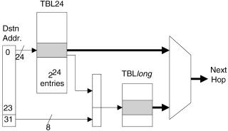
13.6.1The DIR-24-8-BASIC Scheme
The DIR-24-8-BASIC scheme makes use of the two tables shown in Figure 13.12, both stored in DRAM. The first table Žcalled TBL24. stores all possible route prefixes that are not more than 24 bits long. This table has 224 entries, addressed from 0.0.0 to 255.255.255. Each entry in TBL24 has the format shown in Figure 13.13. The second table ŽTBLlong. stores all route prefixes in the routing table that are longer than 24 bits.
Assume for example that we wish to store a prefix, X, in an otherwise empty routing table. If X is no more than 24 bits long, it need only be stored
Fig. 13.12 Proposed DIR-24-8 BASIC architecture.
ROUTE LOOKUPS IN HARDWARE AT MEMORY ACCESS SPEEDS |
379 |
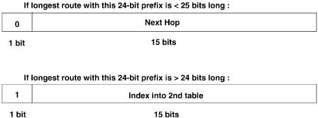
Fig. 13.13 TBL24 entry format.
in TBL24: the first bit of the entry is set to zero to indicate that the remaining 15 bits designate the next hop. If, on the other hand, the prefix X is longer than 24 bits, then we use the entry in TBL24 addressed by the first 24 bits of X. We set the first bit of the entry to one to indicate that the remaining 15 bits contain a pointer to a set of entries in TBLlong.
In effect, route prefixes shorter than 24 bits are expanded; for example, the route prefix 128.23r16 will have entries associated with it in TBL24, ranging from the memory addresses 128.23.0 through 128.23.255. All 256 entries will have exactly the same contents Žthe next hop corresponding to the routing prefix 128.23r16.. By using memory inefficiently, we can find the next-hop information within one memory access.
TBLlong contains all route prefixes that are longer than 24 bits. Each 24-bit prefix that has at least one route longer than 24 bit sis allocated 28 s 256 entries in TBLlong. Each entry in TBLlong corresponds to one of the 256 possible longer prefixes that share the single 24-bit prefix in TBL24. Note that because we are simply storing the next hop in each entry of the second table, it need be only 1 byte wide Žif we assume that there are fewer than 255 next-hop routers this assumption could be relaxed if the memory were wider than 1 byte..
When a destination address is presented to the route lookup mechanism, the following steps are taken:
1.Using the first 24 bits of the address as an index into the first table TBL24, we perform a single memory read, yielding 2 bytes.
2.If the first bit equals zero, then the remaining 15 bits describe the next hop.
3.Otherwise Žif the first bit equals one., we multiply the remaining 15 bits
by 256, add the product to the last 8 bits of the original destination address Žachieved by shifting and concatenation., and use this value as a direct index into TBLlong, which contains the next hop.